|
|
|||||||||||||||||||||||||||||||||||||||||||||||||||||||||||||||||||||||||||||||||||||||||||
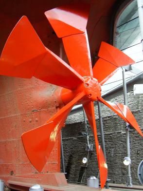
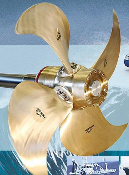
Casting Boat PropellersHow Ship Propeller Blades are Cast
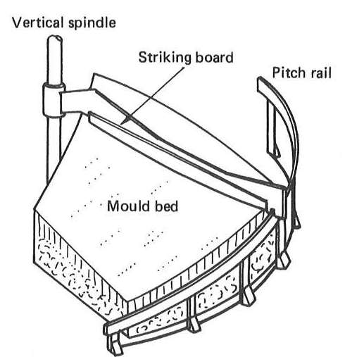
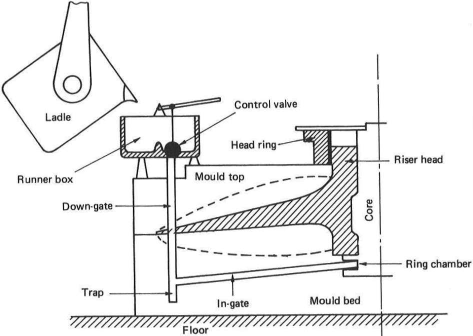
These illustrations from Marine Propellers and Propulsion show how propellers were traditionally molded and cast.
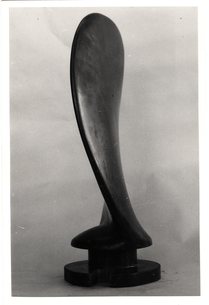
Traditional casting was often done using the Randupson process with uses portland cement as a bonding agent. I like the idea, as portland is widely available. The Randupson process uses 15 to 20 mesh washed silica sand mixed with 10% cement and approximately 5% water. Dry mix the sand and portland for 5 minutes then add the water. Moulds should be air dried for twenty-four hours and may then be dried out more rapidly. The mould is formed around the pattern and allowed to air dry for 24 hours. Once the pattern is removed the mould can be dried with hot air. The blade is cast flat with the boss end making the spure and a vent at the tip. Prior to pouring the mould is preheated the exhaust from the vent temperature is 245 degrees F. The gate is located at the bottom of the boss so as to allow the molten metal to rise gently into the mould which reduces turbulence and so minimizes oxide formation.
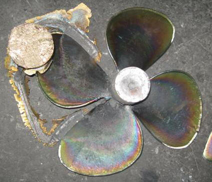
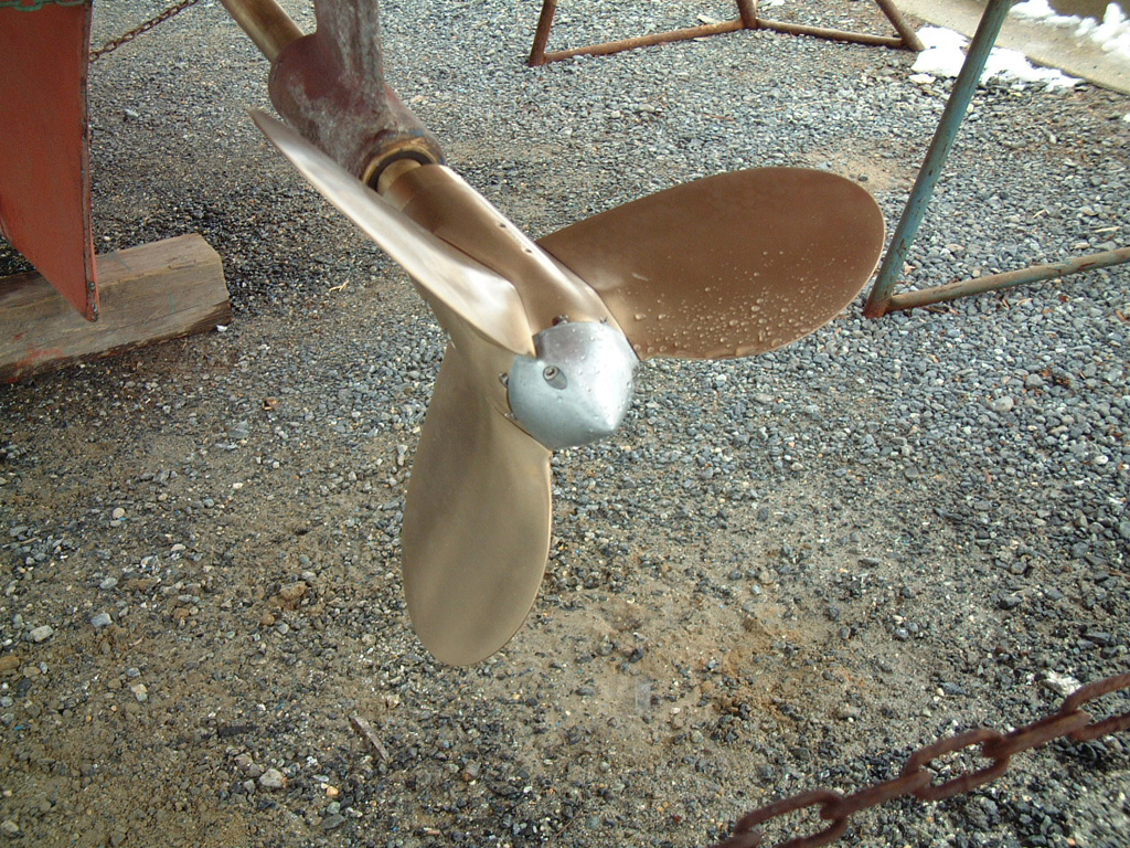
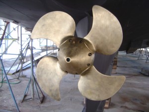
An important detail when casting smaller blades is the addition of a ring around the thin sections at the edge of the blade. The local foundry advised me to do this with my pattern and the photo of the 4 blade prop shows the gating feeding two of the blades and and rings added to each blade. I contacted Brain at Boat City Prop Shop in Oklahoma City. And he'll sell us the Nibral out of his pile of scrap props for scrap metal prices, and while I was there I learned a lot about boat propellers.
Current methods for making propellers takes advantage of sodium silica sand or other resin hardened sands that allow for large propellers to be cast from patterns. Adon, a pattern maker with www.IndustrialShapeAndForm.com shows how a pattern for a 114" propeller is made.
So the next step for me is to start on a CAD design that approximates the original blades, but with the diameter and surface area appropriate for our boat.
Propeller Blade Design
So you think designing a propeller is too complicated. Bull Shit! Don't let the navel architects and arm chair engineer weenies tell you it's beyond your ability. Their problem is they only focus on the latest technology that eked out another .02% of performance by cupping the blade's trailing edge. You don't need that last .02%. You'll not have it after you hit that first log anyway. All you have to do is beat the first propeller that make paddle wheels obsolete. So consider the SS Great Britton with crossed the oceans of the world with it's Frankenstein propeller. Are you going to tell me that you can't do better than that?
Background
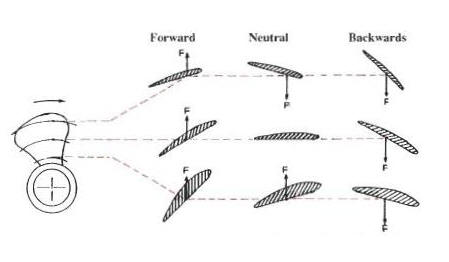
Examples for Variable and Controllable Pitch Props
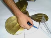
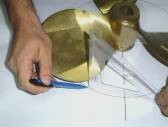
Resources: Manually Measuring Prop PitchFind the difference between the leading and trailing edges of the blade at a point 2/3 to 3/4 radius from the center of the hub.
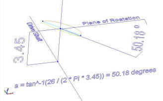
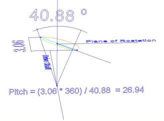
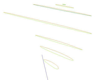
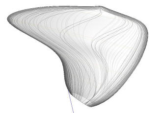
Formula Pitch Angle for a Desired PitchIn order to design Seeker's prop in CAD, we need to find the pitch angle that will create a desired pitch. Pitch Angle is the angle of the pressure face along the line from the leading edge to the trailing edge at a given radius with respect to the plane of rotation measured in degrees. Pitch angle decreases from the blade root to the tip in order to maintain constant pitch. If Seeker's prop was fixed pitch, then it should have a pitch around 25 to 27 inches. So we can optimize the blade for 26" pitch and then the Hundested can adjust it from there. This will make for a prop that has a twist and therefore it will have more drag when feathered for sailing, but it will be more efficient when we are burning diesel, which unlike wind, is not free. Need a great calculator? Use: WolframAlpha.com ...and special thanks to my son Carl who made an "A" in Trig.
The formula for the pitch angle at a specific radius for a desired pitch. Pitch angle = tan^-1( Pitch / (2Pi r) ) where: r = radius So the root of our blade is 3.45" from the center of the hub or r = 3.45, and desired pitch is 26, so: a = tan^-1(26 / (2 * Pi * 3.45)) = 50.18
We can then check it using the Manually Measuring Prop Pitch formula above: Pitch = (Difference between the leading and trailing edges of the blade * 360 degrees) / angle formed between the center of the hub and each of the two measured points. Pitch = (3.06 * 360) / 40.88 = 26.94 ( close enough for me)
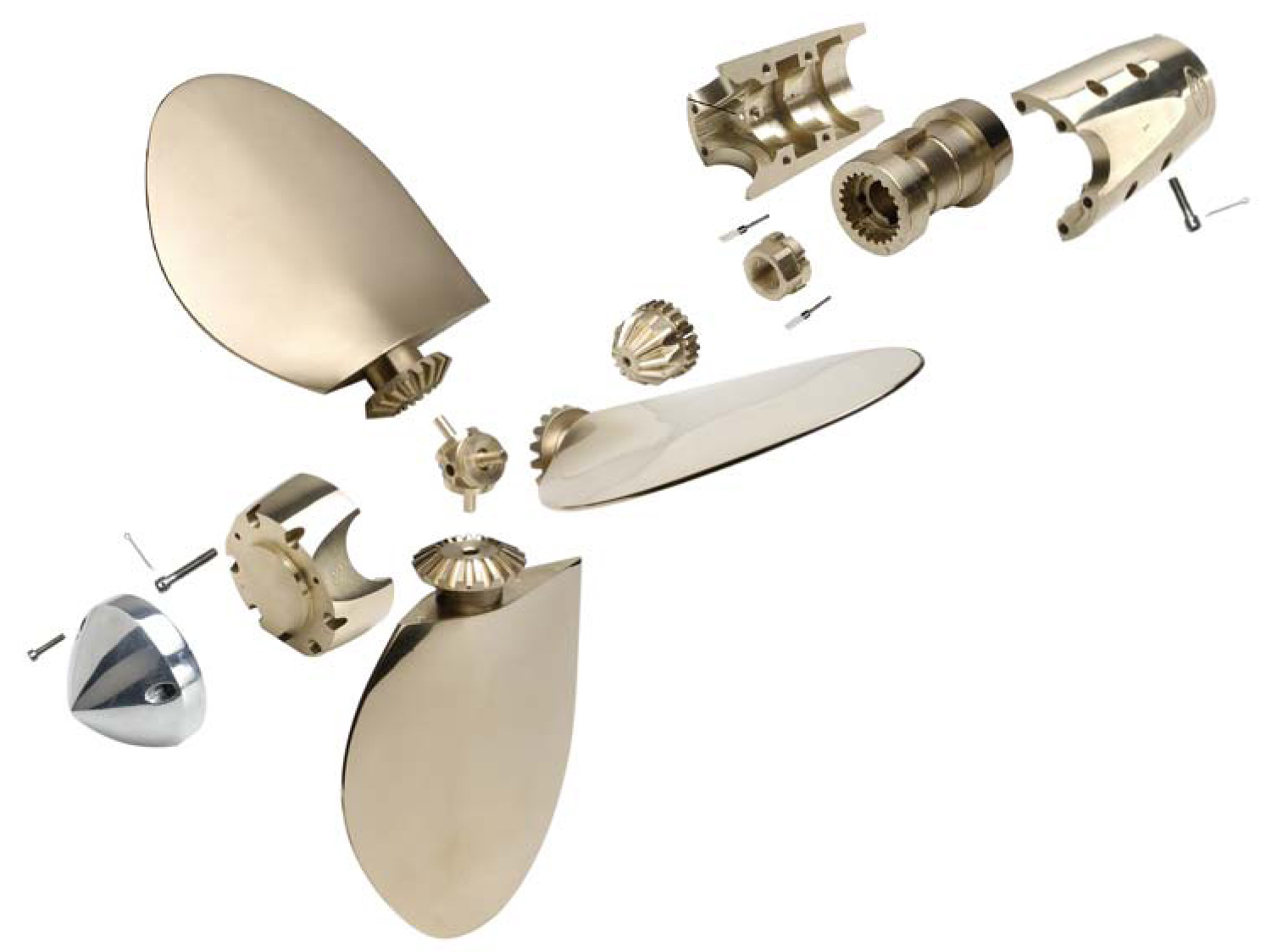
Next the skin is applied. The nipple on the top was added to remove distortion in the skin due to the quick change in shape. It will be cut away later. The normal load on each blade is just under 1,300 pounds and the cross section of the root without any fillet is 3.74 sq in.
|
|||||||||||||||||||||||||||||||||||||||||||||||||||||||||||||||||||||||||||||||||||||||||||

|
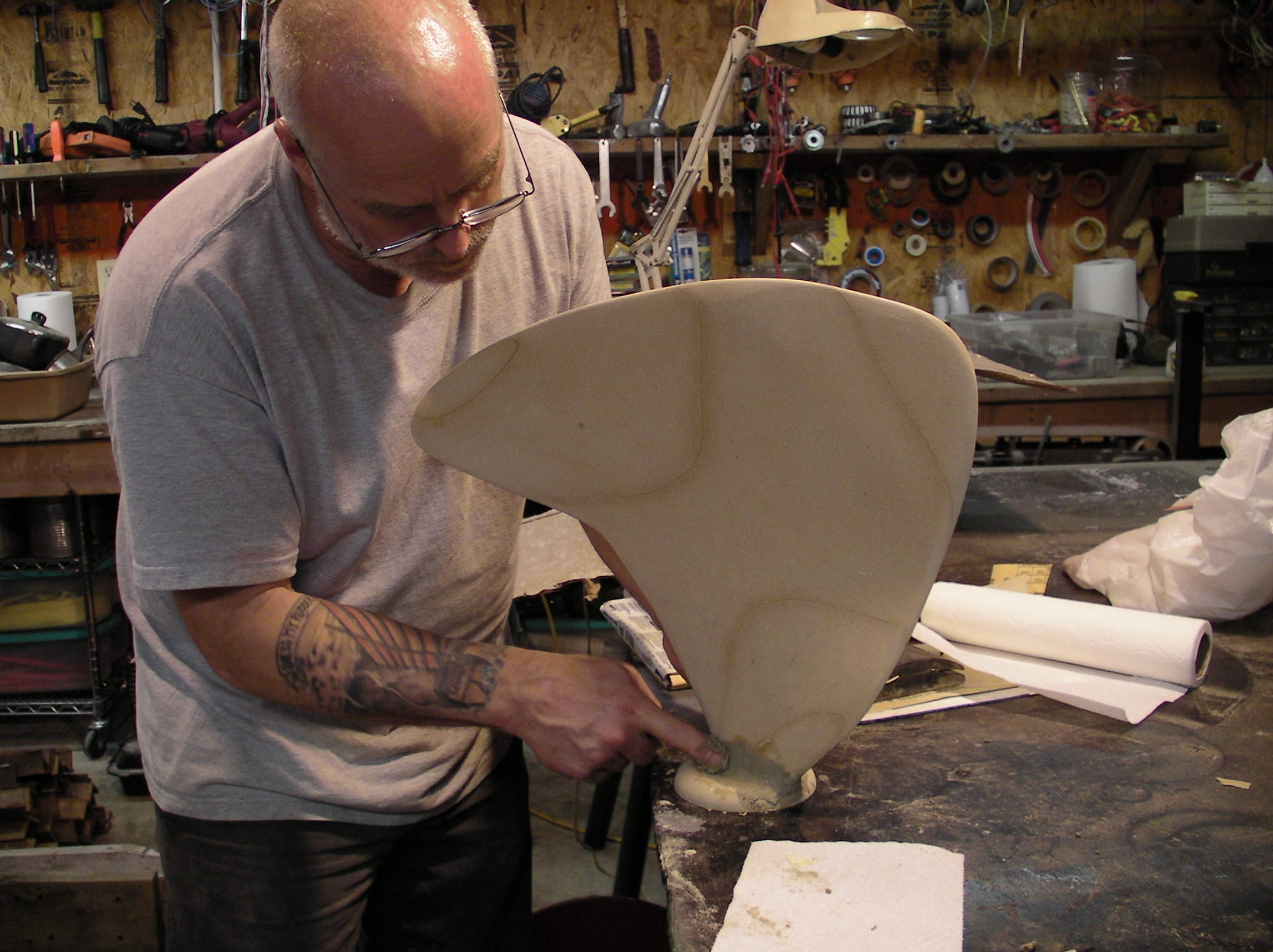
After four test or or failed attempts we got a pattern cut from MDF, or fiberboard.
There is some unwanted high spots on the blade due to the BobCAD software. It did fine where the changes are gradual but it make the tip thinker than planned. However the MDF sands down easily and a slightly thinker tip may be a good improvement when doing battle with sand and gravel.
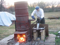
I met with the three of Tulsa Oklahoma's seasoned metal working professions this week and came away prices and stolen ideas for DIY. Jeff Trenholm at Canfield and Joseph foundry supply house worked out a furnace design that will let me melt 60 pounds of NiBrAl and be light enough that we can take the furnace with us on the boat. Then I took may pattern to Jack Pierce at Accurate Machine and Maintenance here in downtown Tulsa, and got a price of $350 each for the finishing lathe and mill work, and Jack directed me to Bob Ramsay at R. & D. Pattern and Foundry Co. just a mile away. Bob like Jack is full of great advice. The cost for have them cast the blade is $750 each. But I need to make changes to the pattern in order to account for shrinkage, the thin edges and the sharp corners on the base so it back to BobCAD to design an improved pattern.
Casting Silicon Bronze
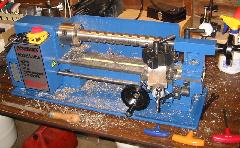
Silicon bronze is much easier to cast that NiBrAl and so it's a good stepping stone. And we need a replacement for the hydraulic distributor ring that is missing from our Hundested controllable pitch propeller, control box. Hundested wants $2200 for the part so making it and a spare for ourselves will more that pay for our brand new 12 x 36" metal lathe.
|
|||||||||||||||
The using the Type K Probe Millivolt to Fahrenheit chart we can find the corresponding Milivolts we need to see on the the voltmeter.
Based on the 5/8" thickness of the part we are casting, R &D Foundry recommended pulling the bronze a 2050F or 45.915 milivolts.
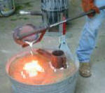
I also picked up 100 pounds of Silicon Bronze (C87500) from R &D Foundry at $5.69 a pound (2012)
|
|
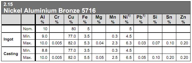
Casting NiBrAl - Nickel Aluminum Bronze
Nickel Aluminum Bronze or Ni-Al Bz, also called "Nibral" and
frequently miss spelled as "Nibrill", is classed as Copper
Alloy and has a melting point of 1913 to
1940F. AA Num: 95800. NiBrAl density is 0.2745674 lbs/cu inch.
It has the same hardness as 316 stainless steel and is the hardest
copper alloy produced for industrial use. There are several
standards that each give it a different code. In the US it's
C95800, Sweden it's 5716. An important feature of C95800
aka 958 is that it welds nicely. The local foundries may have 955 or
specifically C95500 which is a little stronger and a slightly harder
to cast as well, but 958 will do better over years of exposure to
salt water.
Casting NiBrAl into a thin propeller blades may leave voids along
the thin edges and repairs are also going to be needed after hitting
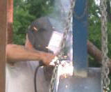
obstacles but NiBrAl can be MIG welded with UTP A 34 N ( ERCuMnNiAl
) wire with 100% Argon gas. AirGas part number for .045" wire
is UTP48102.
|
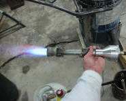
Pyro Meter
http://www.budgetcastingsupply.com/Pyrometer.php BCS #7410
Digital Meter, $49
or use a Volt Meter and the
Type K Probe Millivolt to Fahrenheit chart.
Casting temperature for NiBrAl is 2048F (1120C) to 2300F
(1260C). Rapid cooling of the casting will improved tensile
properties. Contraction will be 2% in the heavy boss section and
less than 1/5% in the blade tip.
|
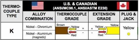
I purchased a couple of Mifco.com thermocouples, item # 004041. The probe must be shielded in steel such as brake line tubing that is welded or crimped closed on the end. The yellow lead from the probe connects to the positive lead from a volt meter. The using the Type K Probe Millivolt to Fahrenheit chart you simply find the milivolts required for the various steps in the process as show below for NiBrAl.
|
|||||||||||||||
Tips: Leave the dross on the melt, take most of it off just
prior to the pour, and push the rest back when you
pour.
Borax for flux or Boric Acid with Sodium Carbonate 50 50 mix; or
better, use
N400CU covering flux
Use a flux tool to push the flux under the surface.
|
Resources
http://www.copperinfo.co.uk/alloys/bronze/downloads/pub-81-designing-aluminium-bronze-castings.pdf
Metal Dynamics -- Don Doss
1145 North Iroquois Avenue Tulsa, OK 74106
(918) 582-0124
R & D Pattern & Foundry Co -- Bob
711 South Wheeling Avenue, Tulsa, OK 74104-3215
(918) 587-2095
Ni Al Bz Ingot Suppliers
Call your local foundries for the best prices.
Atlas Bronze, Trenton, NJ
www.atlasbronze.com
800-478-0887
Federal Metal, Bedford, Ohio
www.federalmetal.com
800.736.6636