|
|
|||||||||||||||||||||||||
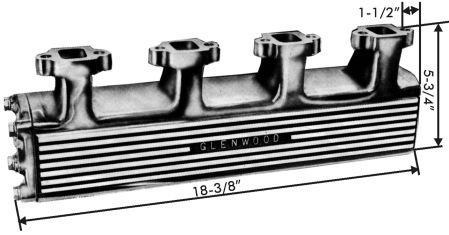
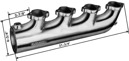
Wet ManifoldThe plan is replace the Ford 7.3's current cast iron exhaust manifolds with a water cooled aluminum manifolds. (1) Marine exhaust manifolds like the one in to photo on a Detroit diesel are generally boxes built around the exhaust pipes coming directly off the cylinder head. They significantly reduce the exhaust temperature, the engine compartment temperature and decrease the engine warm up time. (2) Marine suppliers like Glen-L carry wet manifolds for Chevy and Ford engines commonly converted for used in jet boats. Among the suppliers listed below I found MesaMarine that could custom build the manifolds but I am too afraid to even ask what that would cost. Manifold Warehouse had them, but they cost about $2000 for the pair.
Manifold Suppliers: www.mesamarine.com, www.manifoldwarehouse.com, www.marineexhaustmanifolds.com, www.glen-l.com
How NOT to Build a Wet ManifoldI started by doing some testing with lost wax casting and then switched to lost foam. (1) (2) Lost foam is a process where you first create the part you want in styrofoam. You then encase the foam a shell of mud that is baked into a hard ceramic like crust. Finally you pour in molten aluminum that burns out the foam and fills the void. Let it cool, knock off the shell of mud, clean it up, and you are done. The process failed miserably for me, but it was a great education. You can read more about it here: "Lost Foam Casting".
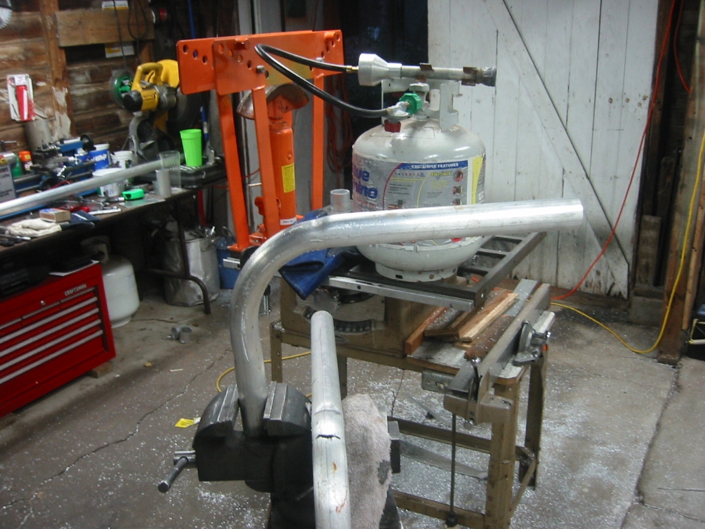
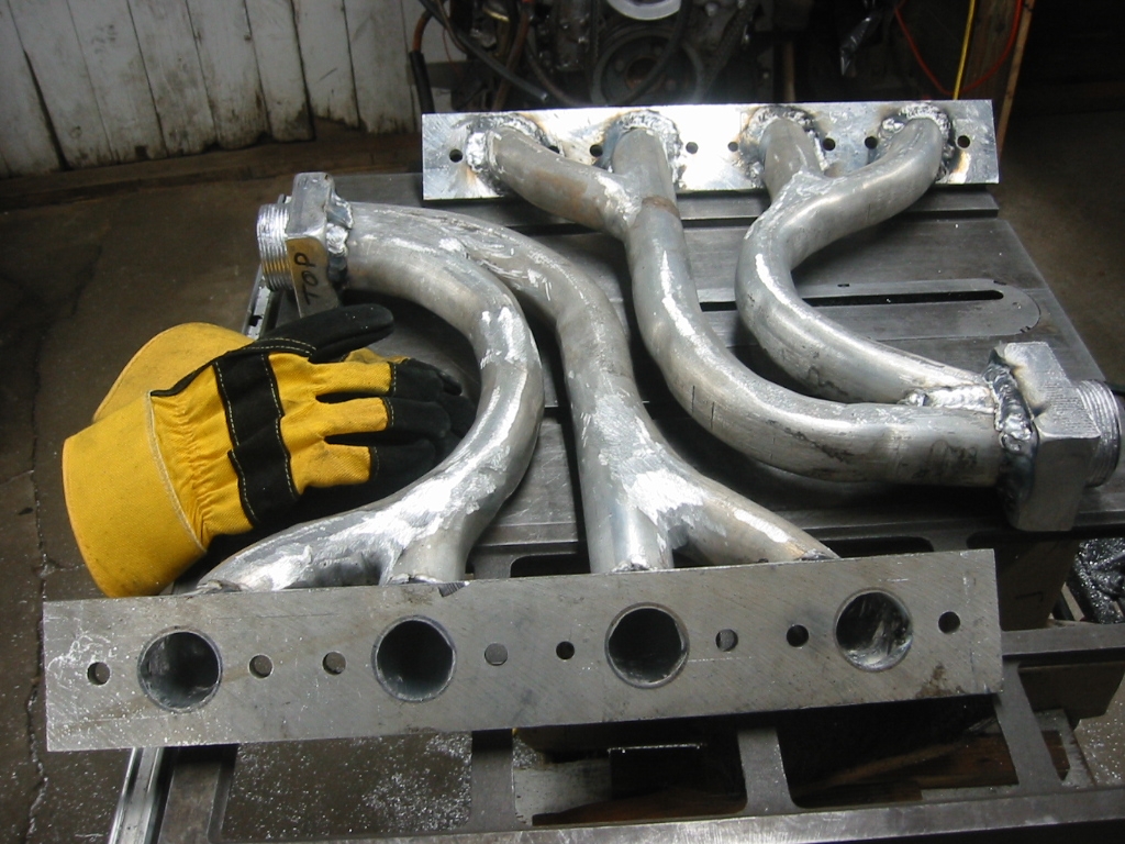
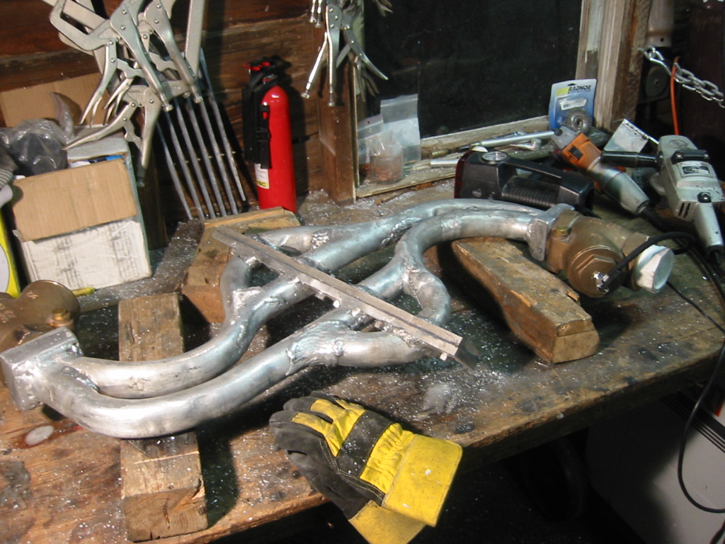
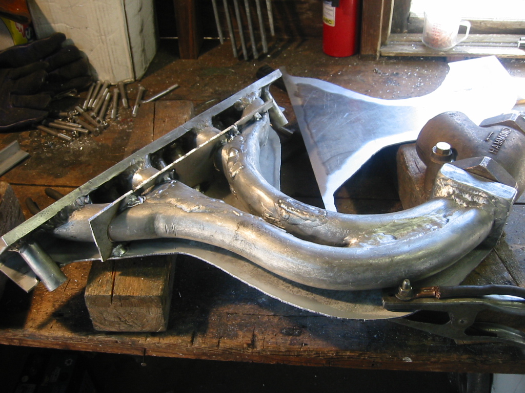
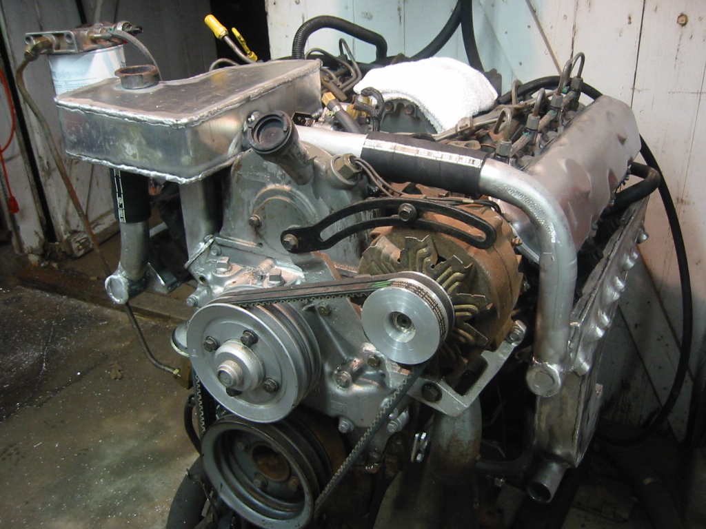
How to Build a Wet ManifoldThe idea now is to bend, cut, and weld a wet manifold together. Harbor Freight put their pipe benders on sale again so I now have a 12 ton pipe bender and I made a couple of practice bends. (1) Preheating the pipe is the trick to bending aluminum, otherwise it tears open once you reach greater than a 20 degree turn. The pipe in lower part of the photo tore open when forced to bend without sufficient heat. Too hot is and the pipe melts without much warning because unlike steel, aluminum does not turn red before it melts. (2) Each manifold is built from 1 3/4 inch pipes welded to a 1/2 plate that bolts to the exhaust head. The pipes immediately direct the flow downward. About six inches from the head the four pipes merge into two pipes, and these continue down in parallel then turn 90 degrees toward the rear where they will join together. I tried to keep the turns gentle and maintain as much volume inside the pipe as possible in order to reduce the drag and pressure. At the bottom end of the exhaust, the pipes connect into a cast aluminum adapter with pipe tread for a 3 inch brass check valve. (3) To cast the adapter, a simple aluminum mold was fashioned from scrap aluminum and the check valve. A plate on the end of a short piece of pipe was inserted into the check and this kept the passage open and only allowed the aluminum to cast the threads of the check valve. Coated the part and the valve threads with a layer of soot allowed the pipe to be removed and the cast part unthreaded from the check valve. The check valve will prevent water from flowing back up into the exhaust when the boat is submerged. Sea water flooding in through the exhaust ports is something to be avoided and the check valves are an added level of safety to prevent this from happening. If everything works perfectly they are not needed. The engine compartment is compensated with ambient air, but there is no way for the ambient pressure easily reach the exhaust side of the engine because the exhaust side is closed off the the valves and piston rings so the check valves ensure that water will not rise up through the exhaust. To keep the check valves cool, the raw water supply from the jet pump will be piped in and injected into the check valves so that it is directed onto the valve gate. The raw water will also further cool the exhaust before it passes through a flexible exhaust pipe that connects the check valve to a solid aluminum exhaust pipe with exits the transom below the water line. (4) Ken "Welderman" who is one of my welding and casting resources had been following my work so I sent him the photo of my manifold and he responded that it looked like I had pin holes and that I should pressure test it. I thought it looked pretty good, but I sealed up the manifold, connected it to a 12 volt tire pump, brushed on some soapy water, and... Have you ever seen one of those bubble machines? Some of the holes were easy to fix but others were persistent. I could grind the weld out, fill it back and the leak would be right back. I burned through and patched a couple of spots so I was sometimes working backwards. After 16 hours of trail and error I finally got all of the holes patched so that the pump reached 40 psi before too much air was leading out the temporary seal between the face plated. The best approach was to lay down parallel welds, and use my stainless steel brush to remove the soot between each pass. The pin holes most often were at the end of the welds, so I started running a final weld across all of the ends, or hooking the end of the weld so it crossed over the previous weld.
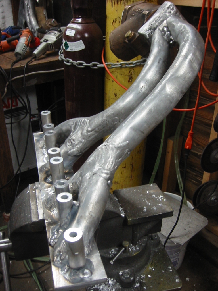
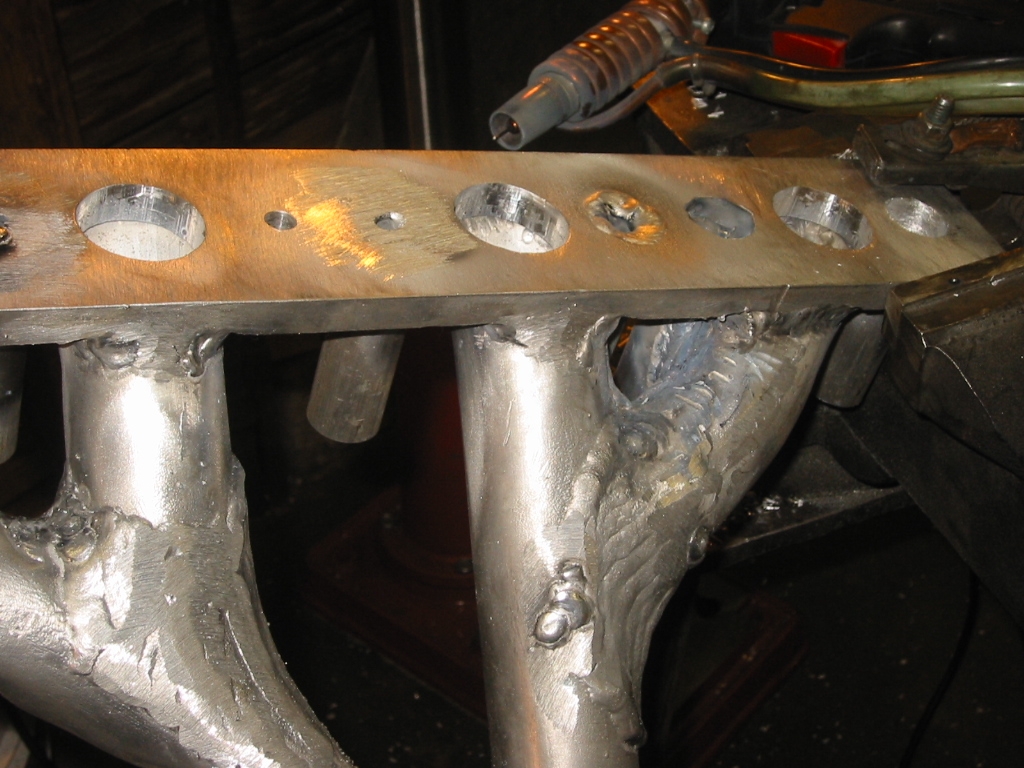
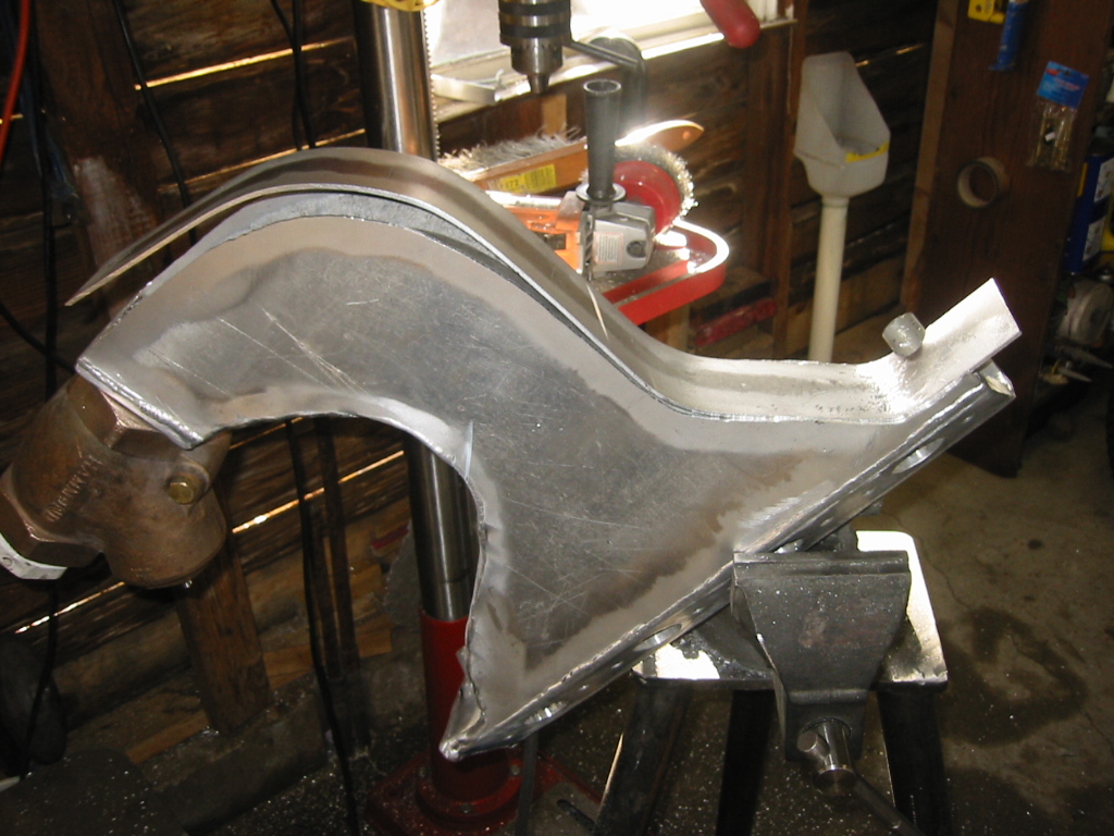
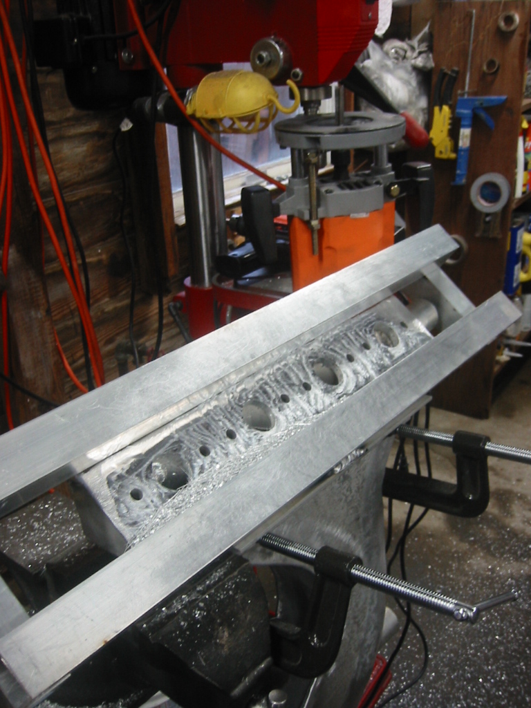
(5) The next step was to weld on bolt passages. These are make from 1 inch rod and drilled with a 7/16 hole that will allow a 3/8 inch bolt to pass through giving the manifold a little bit of room for thermal expansion. Each passage was positioned and then spot welded onto the 1/2 face plate. (6) There was no way to maneuver around the exhaust pipes so 7/8 inches holes were drilled thought the face plate to exposed the bottom end of each passage way. The union of the passage way and the face plate were then welded from within the hole, and the hole was filled with a couple of additional passes. Finally the 7/16 hole for the bolt was drilled out again. (7) (8) The exhaust pipes next are enclosed
by flat sheets in order to form a water box. Engine coolant water
will flow into each manifold at the top front and then be directed
past each of the exhaust ports before flowing down the manifold
where it will be connected with a flexible coolant hose the heat
exchanger build into the hull. The flexible coolant hose and
flexible exhaust hose will allow the engine to move due to vibration
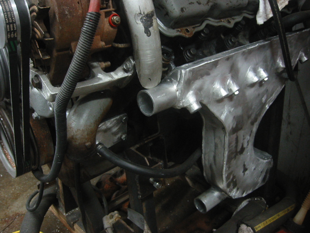
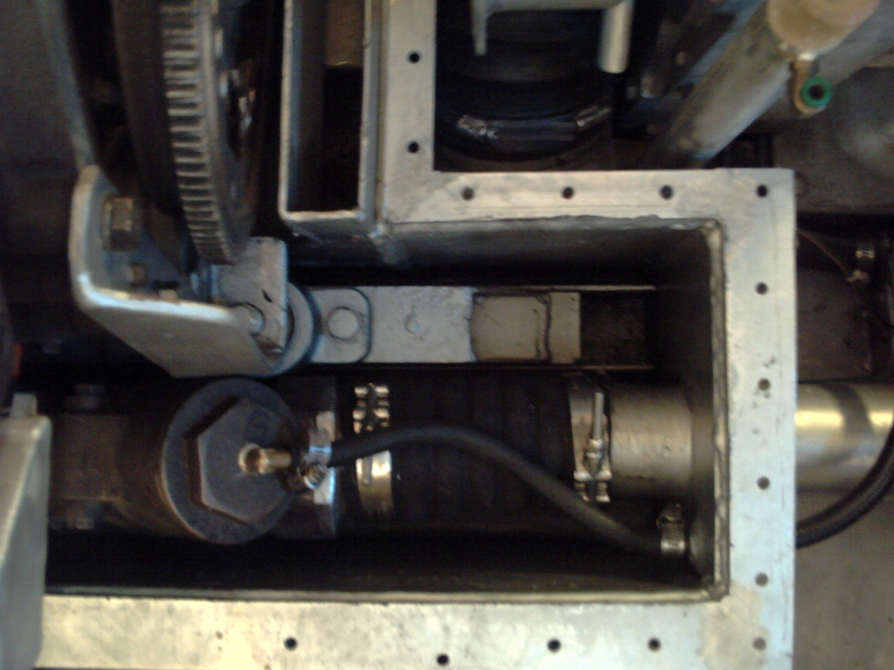
and tork without damaging the manifold. (11) With the fuel pump installed, a reservoir box was
fashioned to hold coolant, provide for expansion, and also serve as
a "T" junction for the flow from water pump directly
beneath it. A fill spout was welded
to the reservoir and short sections of 1 5/8 inch water hose joins
the reservoir to each of the manifolds through 1 1/4 inch pipes that
were welded to the manifolds. (12) Once the engine was installed for it
final fit, a 4" flexable wet exhaust hose was installed to join the
check valve to the exhaust pipe and 1/2" hose delivers raw water
from the jet pump to the check valve. |