|
|
||||||||||||||||||||||||||||||||||||||||||||||||||||||||||||||||||||||||||
Engine and Jet Drive
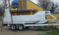
The PlanI started out looking for a used Jet Boat with a fresh V-8, a Berkeley Jet pump with the clean out port on the inside of the transom, a study 2 axel trailer with brakes, and a hull and interior that burned, or perhaps was smashed against the rocks after that last beer. (1) I ended up with a rolled Ford truck with a 7.3L Diesel. (2) And an old Berkley 12JC-A jet pump. I abandoned the gasoline V-8 because I could not easily solve the problem of keeping the gasoline fumes from building up and causing an explosion and fire. Ventilation blowers are the common solution, but the air flow thought the engine compartment while submerged would be inadequate. I considered flooding the compartment with nitrogen, but that would require isolating it from the ambient pressure supply and considerable additional hardware. So, the obvious choice is to turn to diesel power. I tried avoiding this because the old and affordable diesel engines are heavy, and I was not going to find a used jet boat with a Berkeley pump driven by a diesel engine. It would be nice to find an engine already converted for marine use, but that will not likely in Oklahoma. The other problem is diesel engines for cars and trucks turn about 2600 rpm at WOT (wide open throttle) and the Berkeley Jet Pump is designed for 3000 rpm and up in order to pump upwards to 5,000 gallons per minute. I first planned to compensate for this by upgrading the pumps impeller to an A3, which is a bit larger than the common impeller and it would move more water at the lower rpm. In the discussion to follow I explain how I end up with a gear box to solve the rpm problem.
I considered adapting the engine so that it can be submerged without a water tight compartment. The starter and the alternator could survive a dunking provided they were rinsed with fresh water. The air intake will have to be sealed off in either case. The dip stick would need to be sealed, and the few electronics on the engine could be potted in epoxy. The alternative is to construct a tight fitting air tight housing with a top and bottom half. The advantage is additional protection from the elements and longer life. Also less damage when something like a rear main seal fails. Perhaps both plans are best; water proof the engine where it is easy to do, and build an ambient engine compartment around it. Then have sufficient soft ballast in the rear with the engine to compensate for a flooded engine compartment if needed. A V8 diesel engine will weigh at least 940 pounds and another 100 pounds for the Jet Pump, but the compartment that houses the engine will displace about the same amount of water, even if it is build with very little room for the engine. The engine compartment will be an engine shaped box with a top and bottom section, and made water air tight with a gasket and locking clamps. Ambient air will compensate the compartment just like the cabin. At this point I know the engine will be cooled by a "close system" with a heat exchanger. I think I'll build the heat exchanger into the hull since it is already one side of an aluminum box anyway and it will eliminate the need for a raw water pump that would normally move raw through the heat exchanger. I also plan to cast my own water cooled exhaust manifolds because I am cheep, it looks like fun, and I need the exhaust to exit at the lowest possible point since the water will be kept out of the engine by ambient air pressure inside the engine compartment. The water that normally flows out of the top of the engine will connected to a Tee and then flow through the right or left exhaust manifold before entering the heat exchanger. The heat exchanger will be built into the hull on either side of the engine and join back just before returning to the engines water pump. Connecting an aluminum exhaust manifold to a cast iron block will make cracking a potential problem due the thermal expansion differences, but that is something I'll have to live with. Once the exhaust passes thought the manifolds it will be piped downward and water then injected into the exhaust.
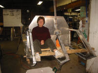
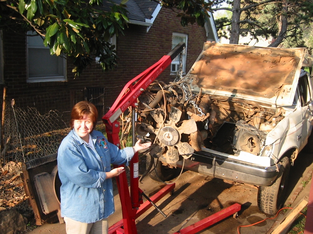
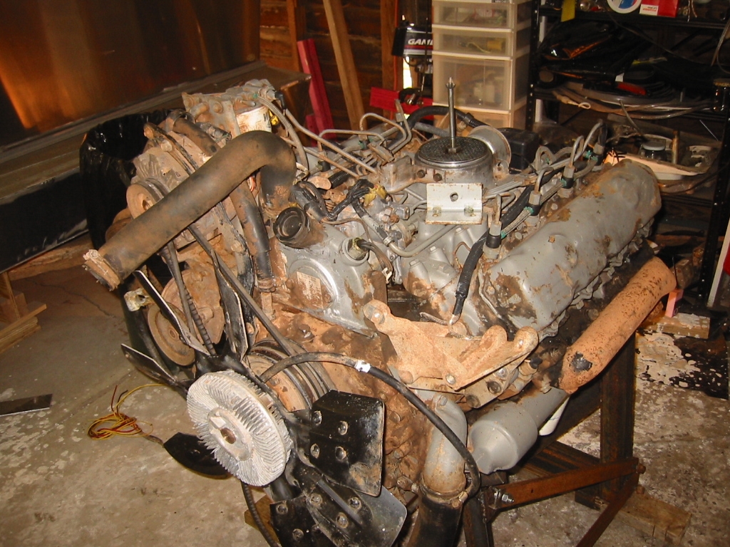
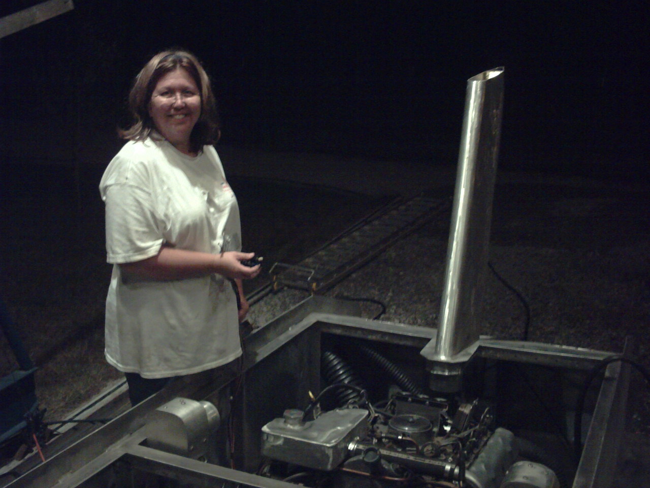
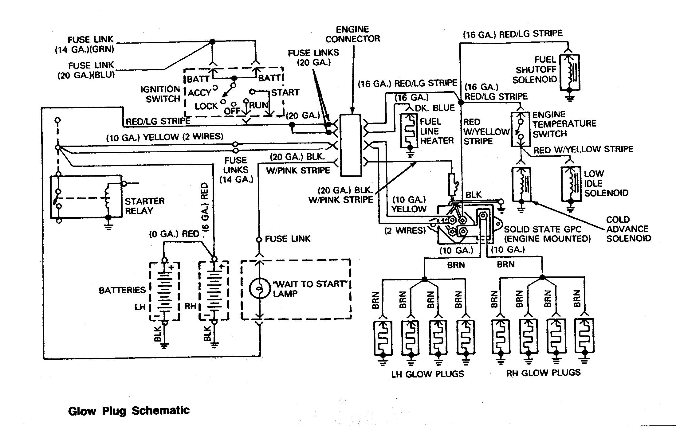
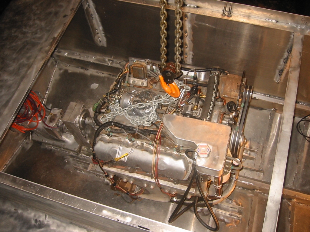
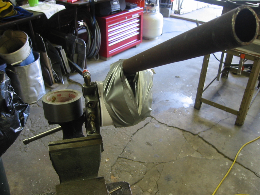
Engine RemovalEngine Removal is a lot easier when you have no intention of putting it back but it was a first for me and only possible after I found a good "Engine Extraction" article on www.thedieselstop.com. This is my first time pulling something bigger than a VW engine, and the lessons learned were; #1 the clutch stays with the engine so use the pry bar on the back side of that, and #2, it won't budge until you jack up the front of the transmission. What a mess! 15 years old and I don't think it has ever been given a bath or an oil change. But for the money it will do fine for a prototype engine. Roger - The only guy who bid with me on eBay and one of the nicest guys you'll ever meet purchased the rest of the truck from me for $250 so he could use the parts for a 4 x 4 project. Then he drove all the way from Huntsville Alabama to Tulsa Oklahoma to pick it up. God bless him for setting an example for my wife! It's people like Roger that make my foraging look tame. So the cost of the engine? Purchase price for the truck: $790, plus $150 in fuel and mileage to go get it in Alva Oklahoma. Plus $120 for the speed trap in Enid, Oklahoma manned by your typical fat ass, red neck, hick town, useless cops. Less $250 salvage value for the rest of the truck, plus $35 for a water pump that was obviously shot and my starting cost is $845. (2) I botched together an engine stand and after $8 at the car wash and 6 cans of engine degreaser I can see the engine. I also see lots of things that are going to have to be changed. The engine turns over now. The oil is changed, the fuel and cooling systems have been rigged and it turns over nicely, but I still need to figure out the electrical system Good-old Roger is going to send me the Engine electrical schematic which is not included in the Chilton manual.
She's a Runner!After making several modifications the old girl started. Not only does she start and run, but it took care of the mosquito problem for the entire neighborhood. After replacing the glow plugs, injectors and having the fuel pump rebuilt and adjusting the fuel pump timing she is much better. Read more here: Engine Tune-Up
See the Movie and hear her roar. That clanging sound when she idles is the check valves on the exhaust flapping open and shut.
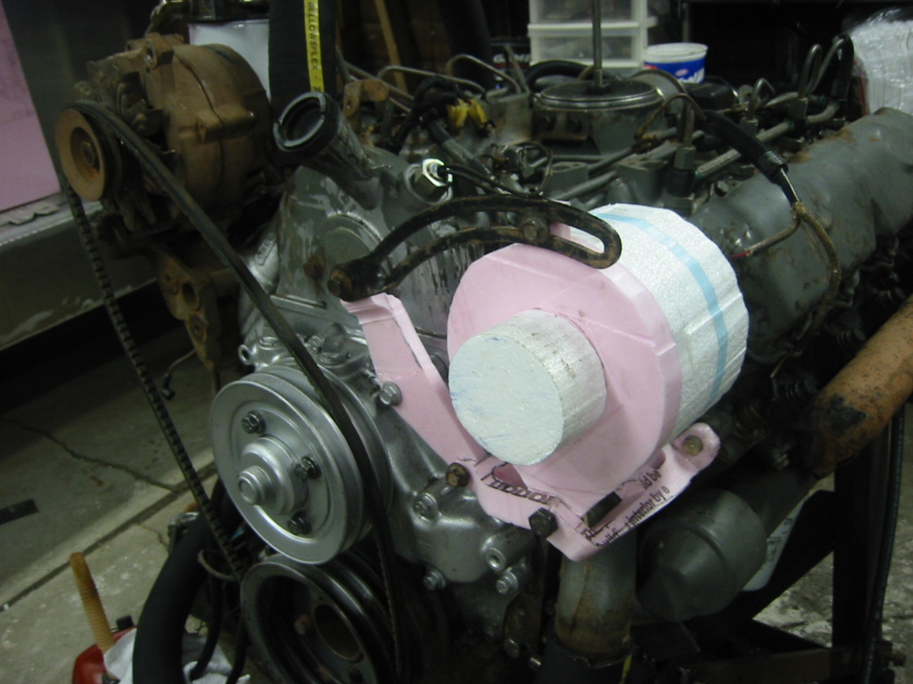
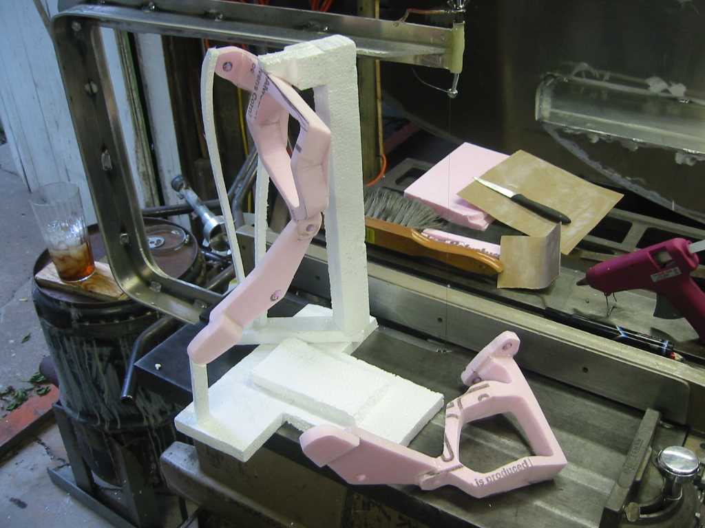
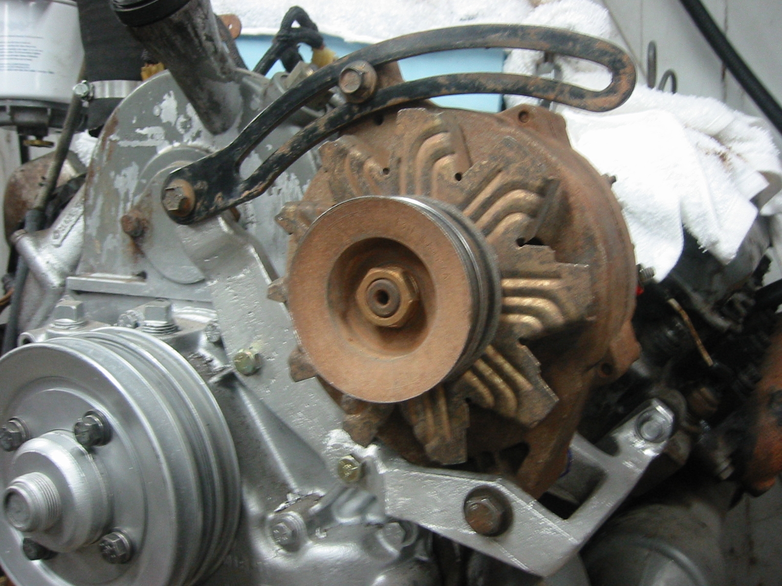
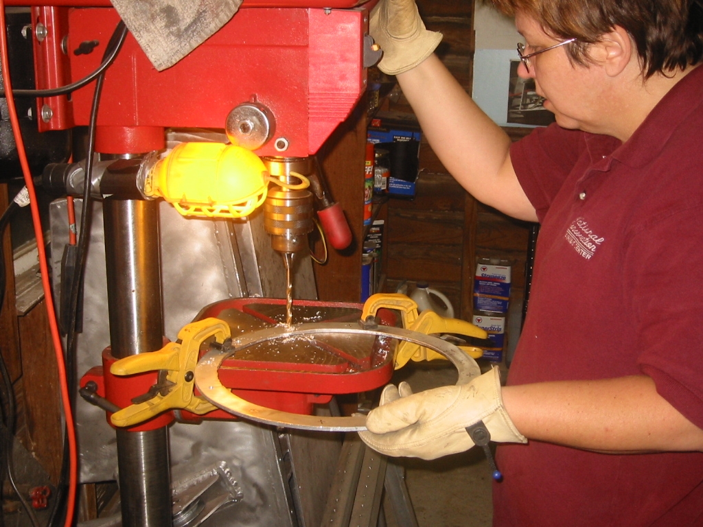
Relocating the AlternatorWhile waiting on Longnecker to rebuild the fuel pump I moved the alternator so that it is lower and a litter closer to the engine in order to reduce the volume required by the engine compartment. A new mounting bracket will be cast in aluminum using a lost foam technique. (1) The photo shows a foam mock-up of the alternator supported by a custom foam bracket. The bracket then servers as a model for making a couple of cleaned up versions. (2) Gates and vents are added, the the foam will be coated with a mud shell before molten aluminum is poured in burning out the foam. (3) Finally the part is clean up and installed into its new home. The entire process takes days to compete and you can see the details of the Lost Foam Casting page under "Secrets of the Lost Foam".
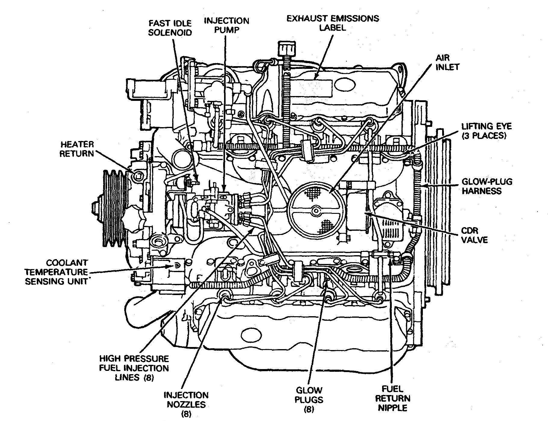
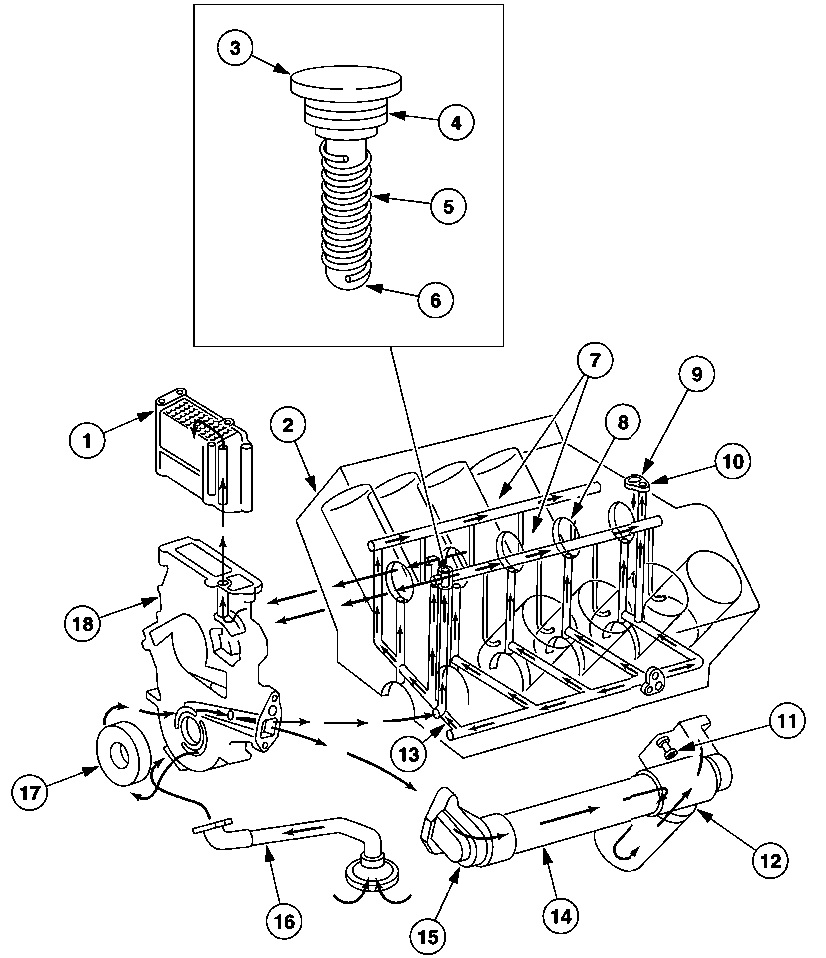
Engine Diagram - 1989 Ford 7.3L Diesel
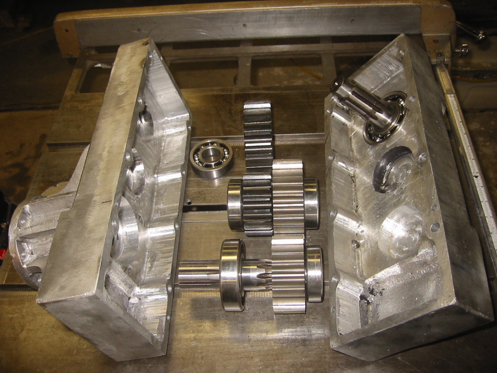
Building a Gearbox
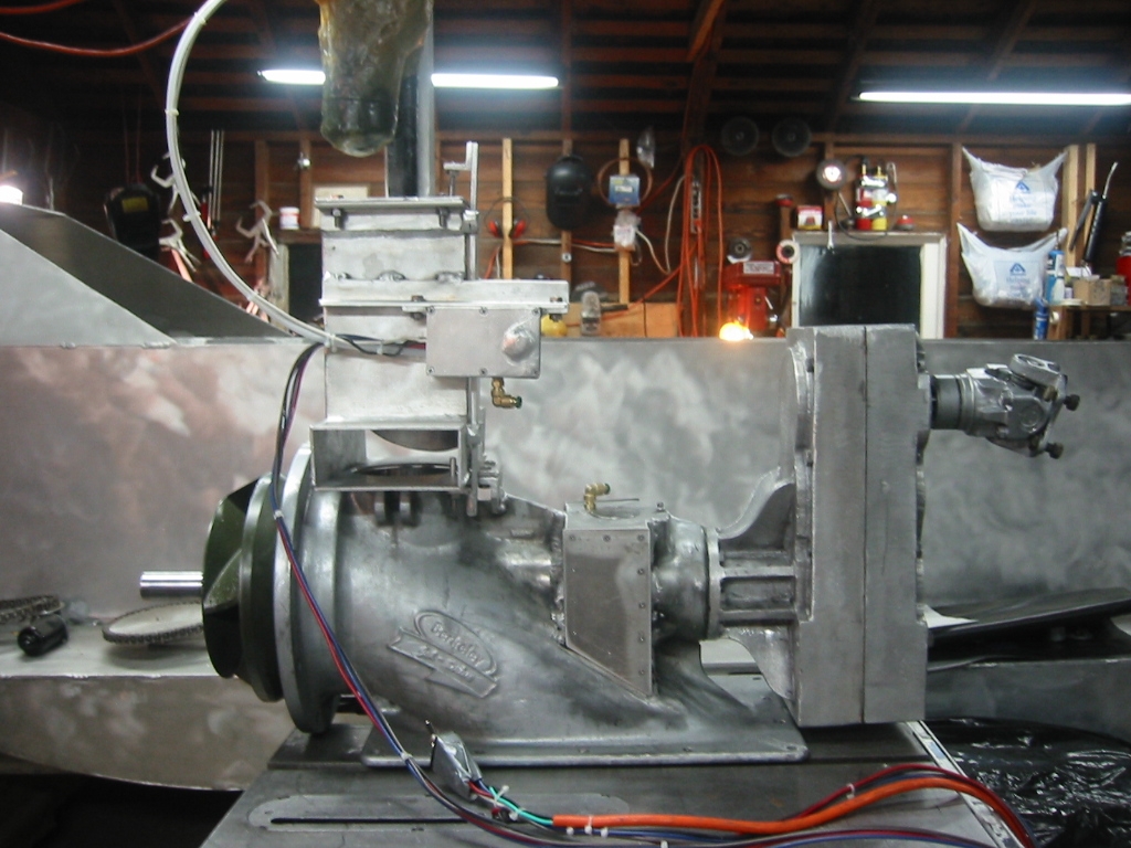
Needless to say the Berkeley Jet Pump was not intended to be connected to a Ford 7.3 Diesel. But if they can make gay marriages work then this should be easy. The drive shaft is about 7 inches lower that the drive shaft for the Ford 7.3, and the pump needs to turn 4000 rpm when the engine is doing about 2000 rpm. The choices are to raise the jet pump, lower the engine, or build a custom gear box that corrects for the misalignment as well as speeds up the rpm. Read more about it here: Gearbox
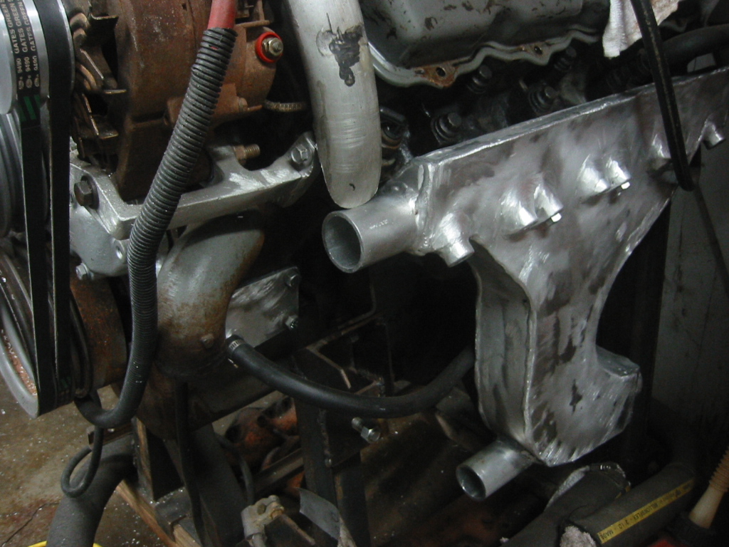
Building a Wet Manifold and Exhaust
A wet manifold is and exhaust manifold that is water cooled. It is easily confused with a "Wet exhaust" which is water that is mixed into the exhaust in order to cool the exhaust. In my case I have both. My wet manifold unlike normal wet manifolds, vents the exhaust down, and then through check valves that help prevent flooding when submerged. Raw water is then added to the exhaust at the check valves to keep the check valves cool. Read more about it here: Wet Manifold
Building a Heat Exchanger or Hull Cooler as well as an Oil Cooler
Without a radiator the engine needs a new way to get rid of heat. Since this is a aluminum boat, and aluminum is a excellent heat conductor it only made sense to dump the heat into the hull where it is carried away by the water outside. Read more about these here: Hull Cooler
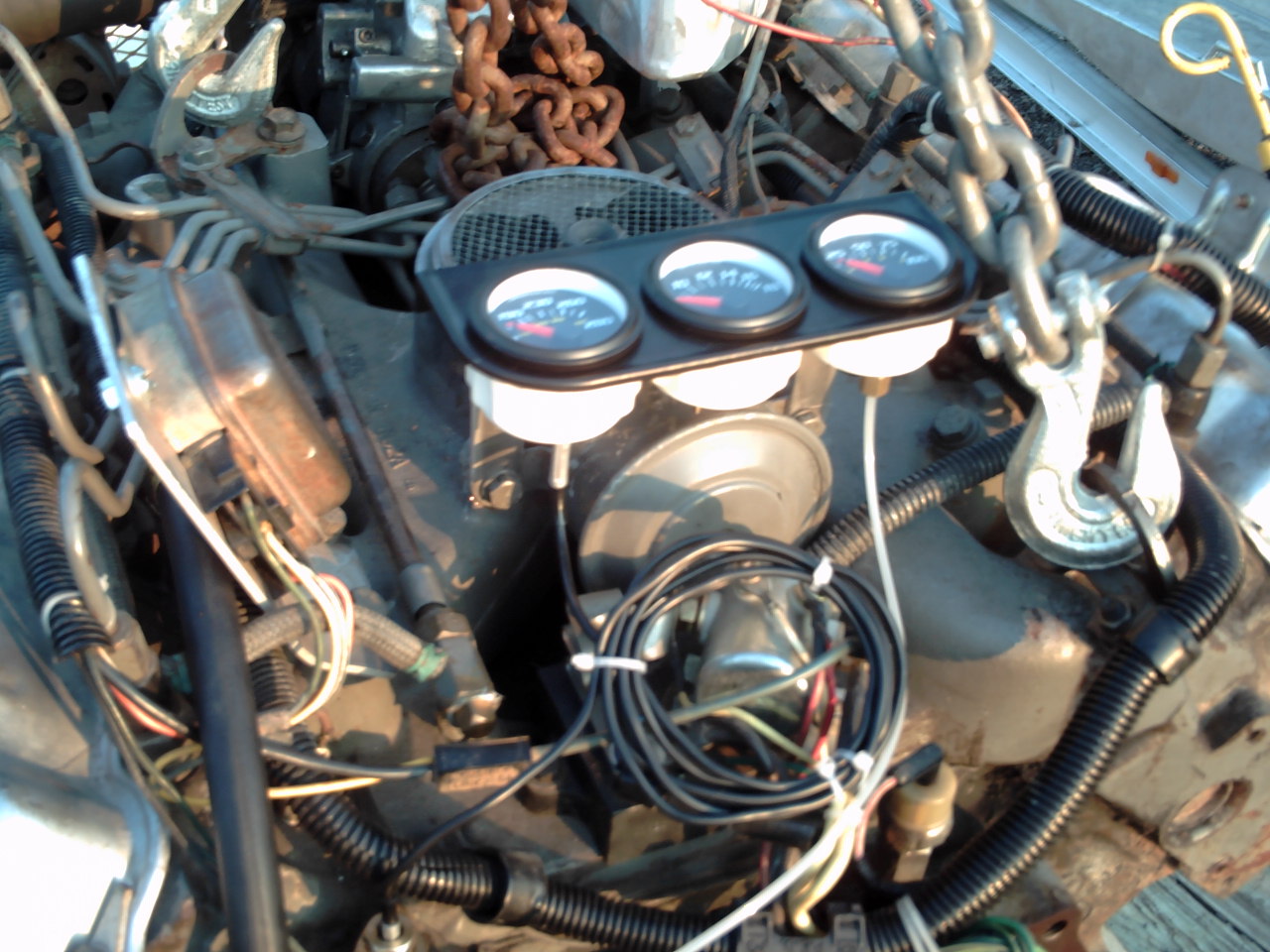
Oil Pressure Regulator
Thar she blows! We installed the engine, started it up for a test and in less than 60 seconds it oil pressure bend the plate that formed the hull oil cooler, rippled open a weld, and blew a gallon of oil all over the back of the sub. When we discarded the stock oil cooler we also discarded the oil pressure regulator but I figured and more oil pressure would not be a bad think right? So now we have build a new connection port where the remote oil filter connects back to the engine block and we now use both of the return oil ports. One is for the engines oil distribution system and the other is just an opening into the block that dumps the oil right back into the pan. The regulator is simply passages drilled through a chunk of aluminum. A ball bearing plugs the passage from the high pressure side to the oil pan return. The ball is held in place by a spring that is adjusted with a bolt pressing on the other end. See the Movie Normal pressure should be 10 psi at idle and 40-70 psi at 3300 rpm. We have ours set to 25 and 80 psi when cold.
|


|
With the jet pump, speed converter gear box, and wet manifolds installed the next step is to mount the engine into the hull.
Mounting the engine consists of converting the mount point on the engine to something that could be used with off-the-shelf marine engine mounts, and building an engine bed that connect the engine mounts to the hull.
Read more about it here: Engine Mounts
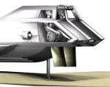
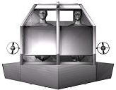
Engine Box
|
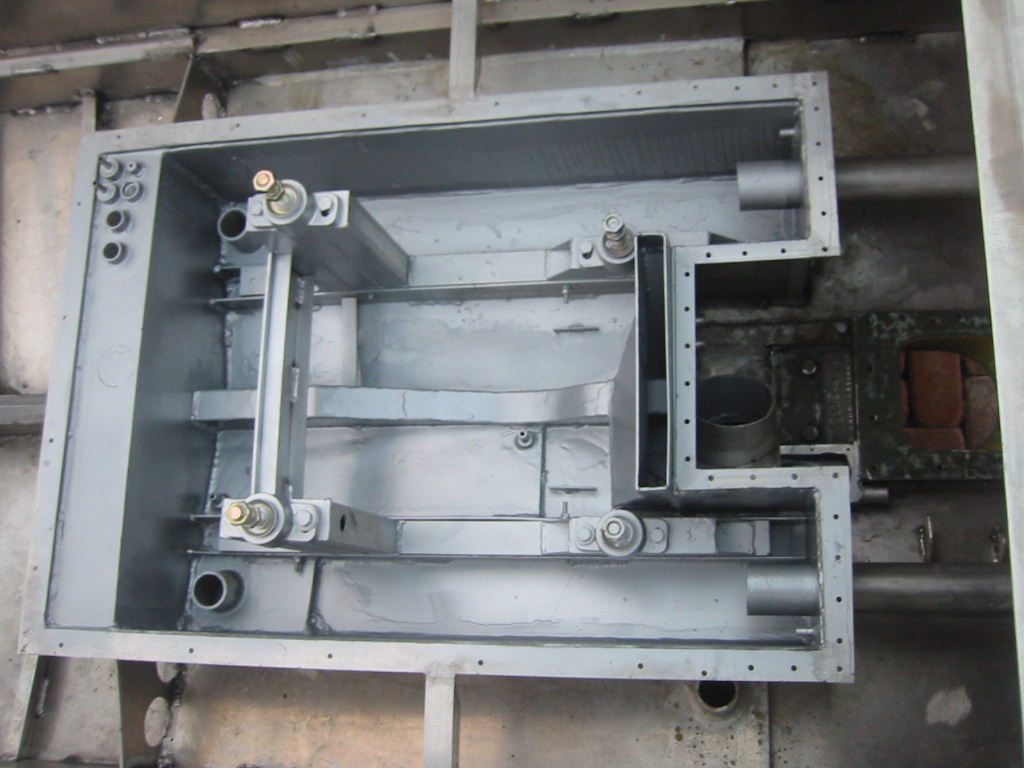
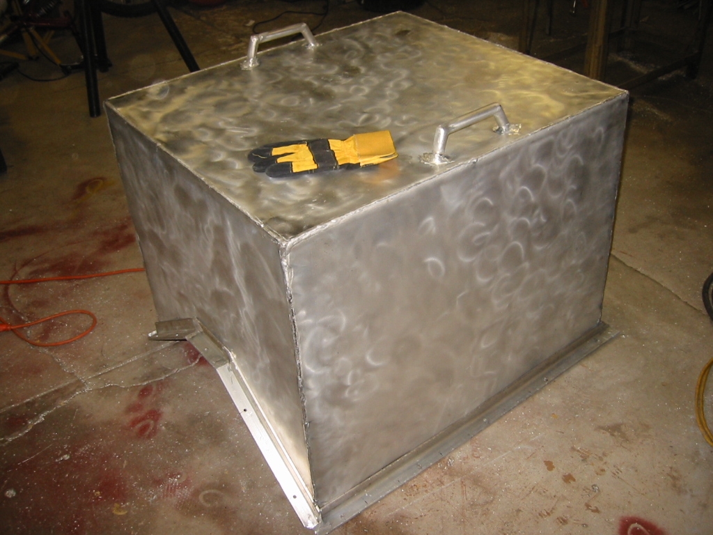
The job of the engine box is to keep the engine dry. The compartment has three sections. The lower section is built into the hull and contains most of the through hull connections for electrical, fuel, exhaust, and bilge water. A center section provides a water tight connection for the drive shaft, and the top is a simple box to cover the engine.
The most difficult problem that it solves is providing fresh air to the engine as soon as the sub breaks the surface.
Read more about it here: Engine Box
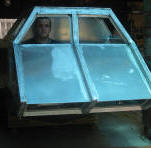
Fuel Tank
|
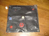
The fuel tank will be just forward of the engine and constructed from an aluminum box that protects a flexible 15 gallon fuel bladder I found on eBay for $70. A normal fuel tank can not be used because the air volume created as the fuel is consumed would change the displacement of the boat. As fuel is consumed from the bladder the bladder will collapse and the volume will be replaced by water. The water is only slightly heaver than diesel so the change in buoyancy between diving with a full tank of fuel, and diving with a nearly empty tank well be very small. The boat will get about 3 mpg so a 15 gallon tank will provide a range of about 45 miles, which is more than enough for the lakes and would easily reach the reach the reefs a few miles off the Florida Keys.
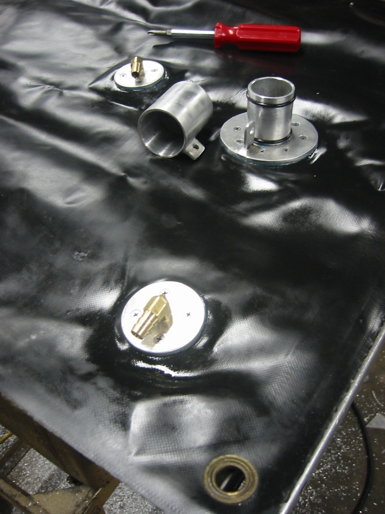
I have now gotten around to replacing the cheap and odd sized plastic fittings with some aluminum fittings. The filler port seals with dual o-rings and the cap is held in place with a pin. Two other ports are for fuel supply and return lines and both are fitted with 3/8 inch 90 degree hose bibs which are threaded into 3/16 aluminum disk that are clamped together with stainless steel screws. The filler spout is uses the same approach except the filler neck is welded to the inside plate and the top plate is a ring.
Remote Oil Filter
|


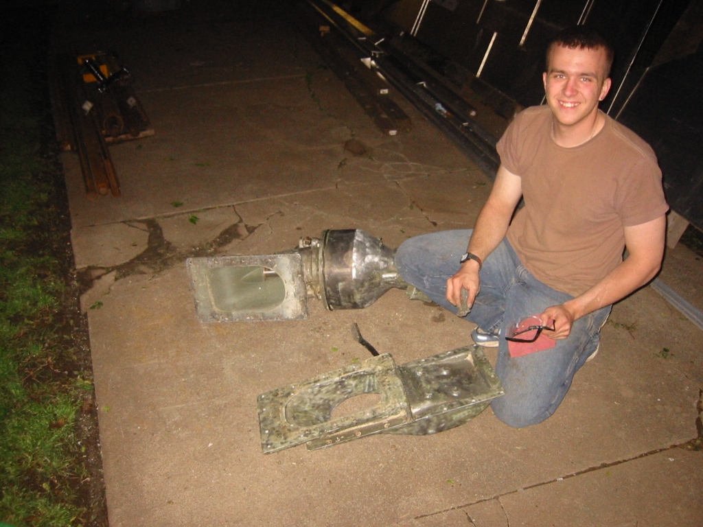
The oil filter on the Ford 7.3 was attached to the oil cooler and located in the path of the wet manifold so it had to go.
(2) Since it was make from aluminum I melted it down to remove the steel nipple that the oil filter threads onto. Then fashioned a new remote mount from foam and imbedded the steel nipple and a couple of machined aluminum nipples. The part was then coated with sheet rock mud and buried in sand before molten aluminum from the old part was pour in and where it burned the foam away. You can see more about it here: "Lost Foam Casting".
(3) After considerable grinding and drilling passages for the oil the part is ready however I am not pleased with the machined aluminum nipples as I think make them too thin.
(4) The casting was a good leaning experience but not worth a second attempt when I can buy a Perma-Cool remote filter mount and fittings for about $45 from www.jegs.com. The mount will fit 3/4"-16 thread filters like the Fram PH8A or equivalent filters.
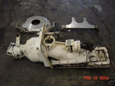
Berkley 12JC-A Jet Pump
(1) I found a Berkley 12JC-A jet pump on eBay for only $270. The impeller is in great shape. I think the good price was mainly due to the bad paint because another pump with fresh paint for $850. There is a lesson to me if I every sell something on eBay again. (2) The pump is looking much better after Carl has stripped away the old paint and epoxy.
|
Jet pumps come with a cleanout port which
is a hatch that allows you to reach the impeller and remove
obstructions. This model of jet pump has the cleanout port located
so that it is inside the boat unlike most pumps that have the
cleanout port outside. Having the port inside the hull is a
really bad design for jet boats because the port is often below the
waterline. Many a boat owner has inadvertently had the
cleanout port open when the boat is in the water, and the result is
what you would expect from having a 4 inch hole in the bottom of
your boat. In my case, sinking the boat is just what I had in mind.
The jet pump cleanout port will be modified so that it can be opened
in order to flood the hull and when the pump is running some of the
water will be drawn from inside the hull until the hull is empty. If
the pumping out process is not fast enough I may add doors that
close over the pump intake port on the bottom of the hull in order
to draw water only from the inside of the hull, but I'll give it a
try without doing the extra work first. It's fair to note that
I have been warned that the cleanout port always has pressure on it,
even when the engine is running and that this plan will not work.
It's my theory that this is true if you were to open the clean-out
port on a normal jet boat because air would quickly be drawn in
causing the impeller to loose its loose it's thrust and allow the
intake water to surge though the cleanout port. In my case air will
not be present so a the low pressure on the intake side of the
impeller will be maintained until the hull is dry, at which point
the clean out port will be closed. Also when the boat is moving
forward at a high rate of speed intake scoop is actually ramming
water into the pump. Slowing the forward momentum would
prevent this from happening.
Jet Pump Cleanout Port Valve
|
Converting the clean out port into and electric valve allowed the boat to be flooded and pumped out using the same valve.
Building the valve required making a two position limit switch, casting a part, welding a housing, and incorporating a linier actuator to raise and lower the valve gate.
Read more about it here: Jet Pump Valve
Other Jet Pump Modifications
|
(1) The stuffing box on the jet pump is designed to prevent water from leaking around the pump's drive shaft. However a drip is fine as it insures that the shaft is lubricated. Just forward of the stuffing box is the thrust bearings. There is a grease zert on top of the thruster bearing housing for the bearings. The problem here is that I need to keep the stuffing in the stuffing box wet and the thruster bearings greased. I also need to supply ambient pressure to the gear box so I closed off the access opening to the stuffing box and the back side of the thruster bearing and added an air line attachment to the top of the new housing. If water in the new housing is a problem then I'll add ports to flood the compartment with gear oil. Gear oil may flow back into the compartment from the gear box anyway depending on the seal around the thruster bearing.
(2) The Berkley Jet Pump came with a rather large transom box that is heavy and does not fit well so we fashioned a simple compression ring that snugly fits around the jet pumps bole on the outside of the transom and compresses a neoprene gasket with 12, 1/4 inch bolts that Kay has taped into the transom.
Resources
www.cpperformance.com/products_jet_drives.aspx Berkley Jet
Pumps, Parts and Information.