|
|
||||||||||||||||||||||||||||||||||||||||||||||||||||||||||||||||||||||||||||||||||||||||||||||||||||||||||||||||||||||||||||||||||||||||||||||||||||||||||||||||||
A Joystick for PropsThe problems with bilge pumps are they are less efficient than props, each pump can only push in one direction, and they have gotten expensive. If you use motors with props you can build an ROV with just three thrusters, one on each side and one for up and down movement. The down side is that you will have to do considerably more work in order to mount a prop onto the thrusters and mount the thrusters onto the ROV. DC Motors and Props
Water Proofing Motors? -- Don't Bother! Having to water proof the DC motors is the biggest reason that people don't us hobby type motors, but most 12 volt DC motors do not need to be water proofed. The majority will work fine when flooded with water, and if you use them in salt water, just rinse them out with clean fresh water when you are done. Antony is a Yahoo robotrov group member from the UK, and he has done extensive testing using DC motors with no waterproofing. The reason this works is two fold. First, all of that copper wire in a motor that looks like it has no insulation actually does have a thin layer of varnish or plastic coating. That helps prevent too much current from passing through the water. Secondly, electricity will always follow the path of least resistance. While water, and especially salt water do conduct electricity, they do not conduct it anywhere as well as copper, so the vast majority of the electricity follows the wires like it should. Motors that have brushes need those brushes to stay in contact with the "commutator" and the pads of the commutator are not insolated, so water inside a motor with brushes will cause more problems, but it will still work. It's a good idea to stretch or change the brush springs so they apply more force than normal. This will help hold the brushes against the commutator when they are submerged. Adding a prop to a DC Motor is not hard to do. There are lots of props available for Radio Controlled (RC) boats from a number of hobby stores. Hobby Lobby at www.hobby-lobby.com has 60mm 4 blade props for under $5. Your biggest difficulty will be finding a prop that perfectly fits the drive shaft of the DC motor you buy. In that case just drill out the prop if needed and glue it to the shaft with 5 minute epoxy cement. You can get low cost DC motors from www.allelectronics.com or other discount electronic suppliers. All Electronics has a DC motor, model number DCM-251 that is 12 volt, 1.3 amp (no load) for less than $4. Antony tested this motor with a 60mm 4 blade prop and found it could pull 16 amps. That is a lot more work that you will get out of a $20, 2 amp bilge pump. If you want to step up on efficiency and reliability then have a look at "brushless" motors. They don't have a brush or commutator exposed to the water. Instead they have a permanent magnet that needs no power to create the magnetic field that turns the drive shaft. Antony has run a KD A22-20L Brushless Outrunner Motor in salt water for days without any waterproofing or any problems. Brushless RC motors require you to also have an Electronic Speed Controller or ESC. The ESC must be able to run the motor in reverse as well as forward. Most ESC units for airplanes only run the motor in one direction. Be careful because the advertisement may say "forward and reverse" but they mean "you can wire it up to run the motor in forward or reverse and changing the direction means changing the wiring". The ESC needs to be able to carry at least as many amps as the motor can consume and you will pay about $25 for a 20 amp ESC. Then you still need an RC controller. The ESC takes a pulsed signal from and RC radio controller or computer servo controller. You can use RC radio equipment and replace the radio connection with a wire. That must be done because radio waves only pass a few feet through water. Or you can get something like a $25, Pololu servo controller and program your computer to run the ROV. If your interested in that route then have a look at the ROV for the Argonaut Jr. A couple of terms you'll want to know before you go shopping for brushless motors. Brushless motors are rated in Kv or the number of RPM (rotations per minute) to the Voltage. So a 1000Kv motor at 10 volts will spin at 10,000 rpm. Generally for use in water, slower is better, see cavitation. There are also "inrunners" where motor is mounted and shaft inside the motor spins the prop; what you would normally expect. And there are "outrunners" where one end of the motor is mounted and the body of the motor spins, so you attach your propeller to the outside of the motor. That is easy to do if you are using old computer power supply fan blades. Generally inrunners are high Kv (ex. 3200-5600Kv) designed for high rpm (50,000rpm) - they can be used in direct drive with small props, but are often geared to drive bigger props. Generally outrunners are much lower Kv (ex. 800-1500Kv) and higher torque (in part because of the larger rotating mass of magnets and bell), and so can be used as direct drive with large props. And finally BEC, or battery elimination circuit. This circuit can be used to powers and servo motors instead of connecting them to the battery. It's really intended for airplanes, because the BEC also has logic which senses the battery voltage, and at the low end of voltage, the BEC will shut down power to the propeller assuring the servos which provide steering, get the last bit of electric power. If you still want a sealed motor then you can take the motors out of bilge pumps and replace the impeller with a prop. Some bilge pumps are have replacement motors that are sold without the pump housing and that will let you save some money.
|
||||||||||||||||||||||||||||||||||||||||||||||||||||||||||||||||||||||||||||||||||||||||||||||||||||||||||||||||||||||||||||||||||||||||||||||||||||||||||||||||||


| SPST Single Pole/Single Throw |
|
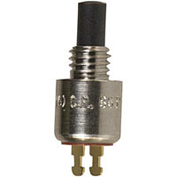 |
Push button switches are either momentary or push on, push off. Momentary push buttons are good for controlling bilge pumps. They are also the type of switch that is used in arcade type joysticks. There is one SPST switch for each direction of movement. |
| SPDT Single Pole/Double Throw |
|
|
Toggle switches come in two position, where the
handle is either on one side or the other. And they come
in three position where the handle is in the
center or to one side or the other. They can also be
momentary, so when you let go the handle springs back to
the center. This toggle switch is: (on)-off-(on)
which indicates that it is three positions where the
center position is off and the side positions are
momentary. The parentheses are often used to
indicate a momentary position.
An (on)-off-(on) toggle switch would be perfect for controlling two bilge pumps that thrust in different directions, such as up and down. |
| DPST Double Pole/Single Throw |
 |
|
Do not make the mistake of using two DPST push button switches to run a thruster with a prop. One switch to run the motor forward and another to switch the negative and positive wire and run the thruster in reverse. If both switches were accidentally pressed at the same time the negative and positive terminals of the battery would be connected directly together and something is going to get hot and burn up very quickly. Keep in mind that car batteries have about the same amount of energy as a half stick of dynamite. |
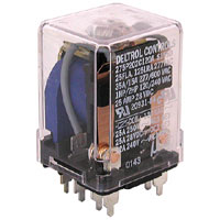
| DPDT Double Pole/Double Throw |
|
|
A DPDT (on)-off-(on) toggle switch is good for
running a thruster in either forward or reverse.
 A reversible thruster on each side of an ROV and a third in the middle to move it up and down is all that is needed. Only three DPDT (on)-off-(on) toggle switches could be mounted in a box to provide the controls. |


|
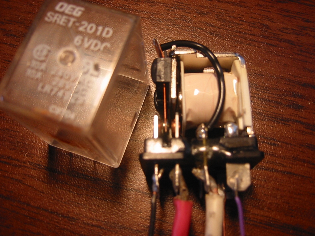
The Magic of Relays
A relay is a remote controlled switch. When you press a button on a control box or move the joystick so it pushes a button then a small electrical charge flows down a wire to the relay on the ROV. That small current flows through a coil of inside the relay and creates a magnet. The magnet they causes all of the poles to switch to the other throw. Since a relay can be DPDT then, a simple SPST switch in a joystick can trigger a DPDT switch on the ROV.
Relays have another advantage. The wire you use to power the thruster motors on the ROV must be large enough to carry the required power. Most 500 gph bilge pump motors need about 2 amps. If you have 3 bilge pump motors then the total draw will be around 6 amps. To get 6 amps from a 12 volt battery to your ROV which is 60 feet away from the battery, you will need two 12 awg wires, like those in a heavy extension cord. The wires running between the joystick and the relays can be much smaller 22 awg wire, like the wires inside a computer network cable or telephone wire. Together the extension cord provides the power, and the computer network cable provides the control of the power to the thrusters.
If you were to wire up 3 bilge pump motors without using relays then, each motor would need 2 -12 awg wires each. And you would still need DPDT switches to reverse the motors so if you wanted to use a joystick you would still need relays, because the joystick only has a SPST switch.
Whatever you do, you want to try to keep the umbilical of wires between the surface and ROV as small as possible. The bigger the umbilical, the slower your ROV will move. And if there is a current in the water then the current will push on the umbilical and drag your ROV along.
|
|
Why Use a Circuit?
Here is the problem. Say you want to use three reversible thrusters with props. You also want to use a Joystick and not rocker switches. So why not just connect the 4 - SPST switches in the joystick to DPDT relays? Because with just three motors, one is used for up and down, the other two have to work together for left and right turns as well as forward and backwards movement. Pulling the joystick to the left, needs to put the right side motor in forward and the left motor in reverse. However when the joystick is left and forward the left motor needs to be shut off, and the right motor needs to thrust forward so that the right motor can push the ROV forward. Pushing only on the right side will cause the ROV to move forward and turn to the left at the same time. This ability to control your ROV with just one finger is what makes a joystick so nice.
The answer is to use 6 relays and a hand full of digital logic chips
to interface the Joystick to the relays. Provided two of the thrusters
are each mounted on the sides of the ROV, and both thrusting front
to back with the third thruster mounted in the center and facing up
and down to control altitude, the following works well for
controlling the two forward and reverse thrusters. From the diagram
below you can see that when the joystick is pushed forward switch A
will be on and both the left and right thrusters will be turned on
and pushing forward, but when the stick is moved a to the right and
forward then
both switch A and switch B will be on. In that event we want the
left thruster to push forward and the right thruster to be turned
off. This will allow for forward movement but with a turn to the
right.
Key: LeftMotor-RightMotor
Rv = Reverse
Fw = Forward
A,B,C and D = Switches on the Joystick
Power from a small 9-volt battery is wired to each switch in
the joystick. When the joystick closes a switch or two
switches, the power will go to the TTL circuit and the TTL circuit
will decide which thruster to turn on and in which direction.
Truth Table
The first step is to create a Truth Table that shows all possible combinations of the 4 Joystick switches. We'll ignore the up and down switches because they are triggered buy 2 independent switches on the joystick. Both the left and right thruster will each be controlled by two relays. One relay will run the thruster forward and the other will run it in reverse. So the Truth Table has 4 switch inputs labeled A-D and 4 outputs labeled Left Forward, Left Reverse, Right Forward, and Right Reverse. A 0 or 1 indicates the the input or output is either off or on.
| Input from Joystick switch | Output to Relay | |||||||
| A | B | C | D | Left Forward | Left Reverse | Right Forward | Right Reverse | |
| 0 | 0 | 0 | 1 | 1 | 1 | |||
| 0 | 0 | 1 | 0 | 1 | 1 | |||
| 0 | 0 | 1 | 1 | 1 | ||||
| 0 | 1 | 0 | 0 | 1 | 1 | |||
| 0 | 1 | 1 | 0 | 1 | ||||
| 1 | 0 | 0 | 0 | 1 | 1 | |||
| 1 | 0 | 0 | 1 | 1 | ||||
| 1 | 1 | 0 | 0 | 1 | ||||
The next step is to convert the outputs in the Truth Table to
Boolean Equations. For example for equation for the the Left Motor
would read like this: The Left Forward Relay is on when the switch B
is on and A, C, and D are off, or when switch A is on and B, C, and
D are off, or when switch A and B are on and C and D are off. The
shorter and standard way of writing this is to use the asterisk for
the word "and", a plus sign for the word "or" and a line above the
variable for the word "not", but we will use a slash "/" before the
variable instead. The formula would then be:
Left Forward = /A*B*/C*/D + A*/B*/C*/D +A*B*/C*/D
Using a few of the rules of Boolean Algebra, this would then reduce
to:
Left Forward = /C * ( A*/B*/D + /A*B)
Remember your 8th grade Algebra teacher when she told you that you would use algebra every day for the rest of your life? Bunk! Just download a free program to do this work for you. kmap12.exe from www.puz.com/sw/karnaugh uses K-maps to resolve truth tables and is very easy to use, or better yet, you can get Karnaugh Minimizer from http://karnaugh.shuriksoft.com and it will even generate the schematic as seen below.
Using "Karnaugh Minimizer" program we simply fill out the Truth Table for the Left Forward Relay

When you click Ok and the program will fill in the K-map. Then click "Go" and it generates the formula.

Finally select Tools, "Formula => Schematic", and select the type of logic gates you want to use. We have the choice of using "AND and OR" gates which will require us using both types of chips, but we have the choice of using only "NAND" gates. You should know that it is possible to build any digital circuit by just using NAND gates, which means you don't have use but one type of chip. However most of the time you'll need more gates and connecting wires. The schematic for the Left Forward Relay is displayed using each method, and it's clear that we are better off using just NAND gates for this circuit. It might me nice to sit in a class for a few months to learn how to do this by hand.... Wait! No it won't, I did that and I could kick myself now. Just use the software!
|
AND and OR gates
The lines above the letters C and D indicate a "not" gate. If you send voltage, or 1 or an "on" to a "not" gate the other side of the gate will be "off" or no voltage, or 0. And likewise a 0 will be flipped or inverted to a 1. So after the switches go through the appropriate "not" gates they enter the "and" gates. The "and" gate will output a 1 only if all of the inputs are 1. Finally the output from each of the "and" gates goes into an "or" gate. The "or" gate outputs a 1 if any of the inputs are 1. |
AND and OR gates
This circuit does the same thing as the "AND and OR" circuit, it just uses "nand" gates. The "nand" gate is the same as an "and" gate that will output a 1 only if all of the inputs are 1, except a "nand" gate then flips the output. So if all 3 inputs to a "nand" gate are 0, then the output will be 1.
|


Schematic
So below are the schematics for each of the 4 relays using NAND gates. Remember there is 1 Left and 1 Right thrusters, 2 relays per thruster, 1 for forward and 1 for reverse. There is also an Up/Down thruster, but that is a separate and easy problem that does not need a digital circuit.
|
Left Forward = A*/C*/D + B*/C*/D |
Right Forward = /B*/C*D + A*/B*/C |
|
Left Reverse = /A*/B*C + /A*/B*D |
Right Reverse = /A*C*/D +
/A*B*/D |


Basically the circuits for each of the 4 relays are the same. The only thing that changes is the inputs and whether they are are inverted or not. The "not" is actually a gate itself. If you send voltage, or 1 or an "on" to a "not" gate the other side of the gate will be "off" or no voltage, or 0. And likewise a 0 will be flipped to a 1. So after the switches go through the appropriate "not" gates they enter the "nand" gates. The "nand" gate is the same as an "and" gate that will output a 1 only if all of the inputs are 1, except a "nand" gate then flips the output. Finally the output from each of the "and" gates goes into an "or" gate. The "or" gate outputs a 1 if any of the inputs are 1.
Virtual Breadboard Test
The next step is to make sure it works as expected. You could skip this step, but it's a lot of fun! Okay, not a lot of fun; but it is cool. You can download a small freeware program called "Digital Works" written by D. J. Barker at the University of Teesside. And Bob Brown of Southern Polytechnic State University has written a quick tutorial: www.spsu.edu/cs/faculty/bbrown/circuits/howto.html.
The schematic below models the relay control circuit. You can download the relay_schematic.dwm file, open it with Digital Works and test the circuit. You just have to remember that the combinations of switches A and C, and the D and E are not possible with the Joystick. I am also still ignoring the Up and Down thruster part of the schematic.

Buying the Parts
It's time to go shopping! There are lots of suppliers for electronic parts, like Circuit Specialists from my old stomping grounds in Mesa, Arizona. http://store.yahoo.com/webtronics/index.html Check www.allelectronics.com for the more unusual and sometimes very cheap items, like boxes and relays. The parts below are all selected from Mouser www.mouser.com, but Jameco is another good source www.jameco.com.
|

The first time I order my parts I got the wrong type so here are some things to look for. Get CMOS (Complimentary Metal Oxide Silicon) chips and not TTL (Transistor / Transistor Logic) chips. TTL use more power and must have 5 volts where as CMOS chips and work directly off a 9 volt battery. The only down side is CMOS chips are more easily damaged by static electricity. There are two flavors of CMOS chips. Chips numbered like "CD40XX" use metal gates, and work with 2 to 15 volts. Try to avoid chips like "74CXX" which use silicon gates and work with 2 to 6 volts. For more details see this site: www.solarbotics.net/bftgu/starting_elect_ic.html The chips also come with either SOIC, SOP or DIP type pins, and you want DIP. DIP pins will stick through the prototype board and get soldered on from the bottom side. The other types are for surface mounting. The pins should also be .1 inch on center which is the default for most chips but important when buying the prototype board. Most chip cost about 25 cents, but you can pay up to 1 or 2 dollars and get a chip designed to work with more "noise" or static on the line. I think its a worth while investment since I am an amateur builder and because this circuit is going to be driving relays with much more power.
 |
The "NOT" gate is also call an "Inverter" and this one
is a Hex Inverter because it has 6 NOT gates. We only need
to use 4, so it will do just fine. At 25 cents each we can
afford to not use 2 of the gates. Qty: 1 CD4069U Mouser Part Number: 512-CD4069UBCN Fairchild CD4K CMOS Logic DIP--14 Inverter Circuits or 512-MM74C04N with high noise immunity. |
 |
Triple Input NAND with 3 gates. We need a total of 8,
triple input gates so we need 3 of these, giving us one
spare gate, which we could use as a 2 input NAND gate by
simply wiring two of the three inputs together. Qty: 3 CD4023BCN Mouser Part Number: 512-CD4023BCN Fairchild CD4K CMOS Logic DIP-14 Trp 3-Inp NAND |
 CD4011BCN  MM74C00N |
We need a total of 4 NAND gates with 2 inputs. This is
has three, but we have one unused triple input gate not that
we can convert to a 2 input gate by just wiring 2 of the 3
inputs together. So we only need one of these. Qty: 1 CD4011BCN Mouser Part Number: 512-CD4011BCN Fairchild CD4K CMOS Logic DIP-14 Qd 2-Input NAND or 512-MM74C00N with high noise immunity. Note that these ic's use different input and output pins, so be sure you use the right diagram for the one you buy. |

|
Octal Buffer Line Driver Line Receiver 3-State The NOT and NAND gates provide the output signal of 1 or 0 for each relay that we need to turn on and off, but the amperage required to make the coil on the relay work is higher than the 7 mA ( 7 Milliamp = .007 Amp) that will flow through the digital logic circuit. A Line Driver is needed, which actually works the same as a relay. When power is applied to the input, the corresponding output turns on, but it outputs a higher current of 35 mA and voltage up to 7 volts DC and connects that Output pin to the ground. So the coil on the relays will already be powered from the battery and the drain from the coil will be connected to the output pin of the line driver where it will be connected on to the ground when the input is "on". The energized coil on the relay will then close the 3 - 30 amp switch inside the relay which will complete the circuit to the thruster. So the digital logic, triggers the line driver, which triggers the relay, which turn the thruster on. If the reverse relay is triggered the thruster runs in reverse, and if the forward relay is triggered it runs forward, of course. Qty: 1 MC74HC244N
|
 |
Resistors -- It will be necessary to add 4, 500 ohm resistors to the circuit in order to pull-down the gates. "Pulling-down" means to simply provide a very small negative current path to drain a gate in order to get it to switch off. When a switch in Joystick is switched "on" the current from the 9v battery is more than enough to overpower the pull-down current, because the pull-down current must flow through a 500 ohm resistor. The pull-down resistors connect between the negative side of the battery and the input pins on the "NOT" gate that are also connected to the Joystick switches. It's easiest to just buy an assortment of resistors, but at least get a dozen 500 ohm resistors. Only 4 are actually needed. |
|
|
Unless you are very confident in your skills, you will want to have a breadboard so you can test assemble all of the parts and make sure it all works. A breadboard has friction fit holes on .1 inch center which allows you to easily test and correct the connections. The photo shows a test of the Inverter gates. |
|
|
You will need a proto board with holes on .1 inch centers. You will solder the parts to this as well as wires to connect the parts. A 3.75" square board will have more than enough room for the IC's and can be housed in a box beneath the bottom of the Joystick. Circuit Specialists: PC462903 |
|
|
You can optionally get sockets for the ic chips and
solder these onto the proto board. Doing so will prevent
accidentally damaging the chips from excess heat and will
make replacing a chip very easy. Qty: 5 - 14 pin, 1 - 20 pin - Mouser Part Number: 14-3518-10 and 20-3518-10 |
|
|
Qty: 6 DPDT Relays, 4 for the left and right thrusters and 2 for the up and down thruster. The Relays will be housed in a water proof container down on the ROV, and only a small 6 conductors computer network cable will deliver the single to the relays. The amperage of the relays will depend on the size of the motors they control, but the coil needs to be triggered with only 9 volts but 12 volts will do if you power it from a couple of 9 volt batteries. The important thing is to make sure it will carry enough amps without burning up. A small bilge pump motor will pull just over 2 Amps, and possible more if it is converted to a prop thruster and the prop is too big. If that is the case the you are likely going to burn up the motor. Check www.allelectronics.com and www.alltronics.com for these. They will cost about $1.50 each. |
|
|
Car batteries can explode when shorted, so you will be wise to add some sort of a fuse to the power coming from the car battery. A blade fuse and blade fuse holder like the ones in the photo are available from all Auto Parts stores or electronics suppliers. You will need a fuse that is rated for slightly more amps that the total amps your motors are capable of drawing. |
|
|
Other items you will need: Note: It's a good idea to order 2 of everything if you have the budget for it. This allows you to build your solder board without disassembling your breadboard and you'll have spare parts should one get damaged. |


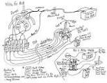
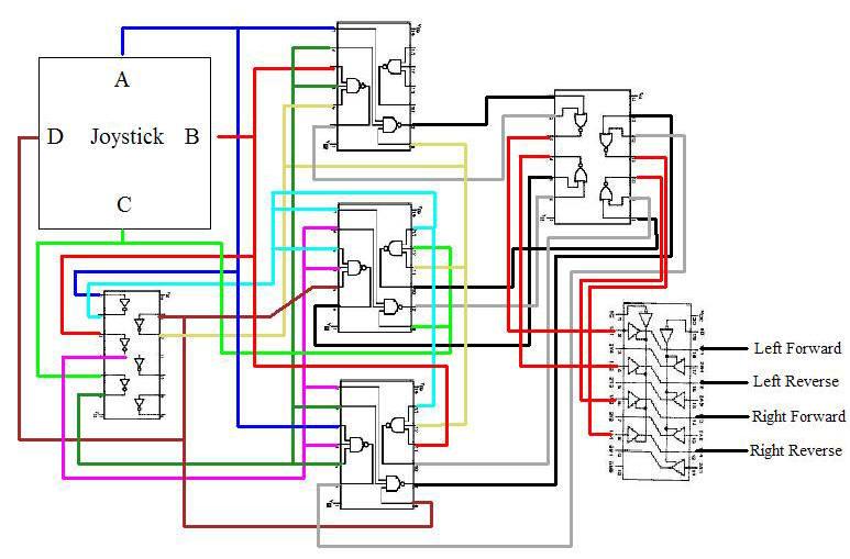
Circuit Wiring Diagram, or How it All Fits Together
The wiring diagram shows where each wire connects to each chip.
In addition to the wires shown, each chip also will have a
connection to the power supply which is a 9 volt battery. The
positive will connect at the pin marked VCC and the negative to the
pin marked "Ground". Pull-up resistors are also not show. I'll work
out where those are needed when putting it together on the
breadboard. Remember that all chips do not have the same pins even
if they are the same type of chip. If you purchased something
other than the parts listed above, you need to check the diagram for
the chip you have and adjust the wiring diagram as needed. It took
me three tries to get it working on the breadboard. I did not notice
that the two different 2-Input NAND gates I found and purchased
actually have different pin assignments.
|


Once the parts arrived its time to put them together on a
breadboard and make it work. I added a 500 ohm pull down
resistors to each of the 4 inputs to the NOT gate. In the photo, I
have one of the test LED's being powered through a 10 amp DPDT relay
that uses a 6 volt coil.
The next step to to move all of this to a proto board and solder it
in place. Here is where it pays off to have purchases two sets of
the parts so you can build and troubleshoot the real board by
comparing it to your bread board. Sockets for the ic chips will help
too, but they are also optional. After several hours I finally had
the board finished. It's powered directly from the 9 volt battery
which also supplies the power for the relays. There are 2 sets of
leads; one set goes to the joystick switches and the other to the
relays. There is 1 wire for each switch or relay and one ground wire
in each set.
Waterproofing
The next step will be to pot the entire board in epoxy in order to make it waterproof and then attach it to the base of the joystick. You can buy non-conductive epoxy that is intended to water proof and also hide your circuit design from others. It actually does the former very well and the latter hardly at all as all epoxies can be chemically removed with epoxy stripper. It's not like we've invented a cruise missile guidance system here anyway. I used off-the-shelf 5 minute epoxy for plastic from the hardware store. After covering my board I waited 24 hours and tested to board only to find that nothing worked. I nearly cursed God and died, but fortunately tested it again after 48 hours and everything was working perfectly. God be Praised! Don't add epoxy thicher that 1/2 inch, because it shrinks when it dries. If it shrinks too much, it can crush the chips.
|
|
|
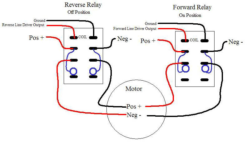
Connecting Circuit to the Relays
The wiring diagram below shows a pair of relays for one of the motors, with the Forward Relay switched on. Most of the time when you see two relays used to run a motor in forward or reverse, one relay will be used to turn the power on and then it feeds through the second relay than has the ability to crisscross the wires in order to reverse the motor. Because the logic circuit has one output for forward and another for reverses and because both should never be on at the same time, we can have each relay power the motor on its own. This will actually help conserve the 9 volt battery because we only power a maximum of 3 relay coils at any one time.
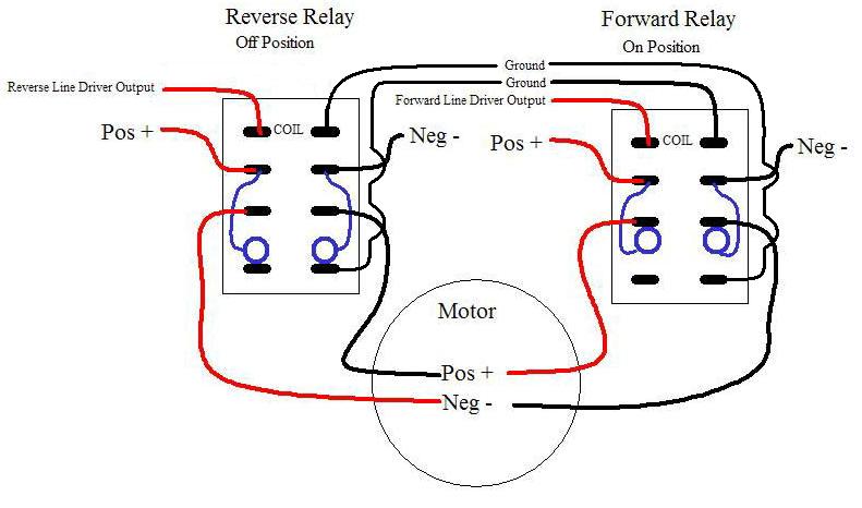
However, mistakes can happen, the joystick could short circuit, the circuit board could fail, or a relay could stick in the on position. If both relays did happen to switch on at the same time it would cause a major problem because all of the batteries energy would star moving across the power line directly from the positive terminal to the negative terminal. Very soon something would get too hot and burn up or worse the battery could explode. A couple of things can be done to prevent this. One is to use the unused normally-closed throws on the DPDT Relays. Routing the coil ground through the normally closed side of the other relay will prevent the relay from energizing it's coil if the other relay is already on.
A fuse it the best safety device. If the motors each pull 2 amps, then the most power ever needed would be about 6 amps. If you put a 10 amp fuse on the positive current flowing out of the battery then if a short occurs the fuse it will burn up and turn off the current before anything really bad happens.